AssayMAP Protein Sample Prep Workbench : Utilities: Normalization v2.0 User Guide : Setting up a Normalization run

Setting up a Normalization run
The Normalization utility includes the Normalization Method Setup Tool that is used to create a method file for the Normalization run. The Normalization Method Setup Tool is a Microsoft Excel-based calculation tool that uses formulas to calculate estimated volume requirements for the samples and diluent based on your input.
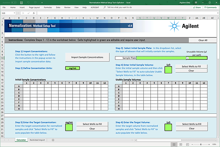
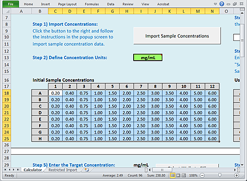
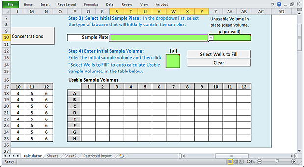
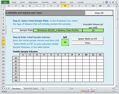
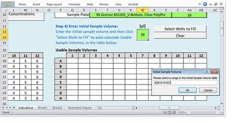
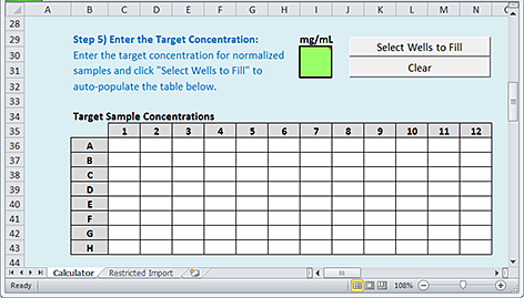
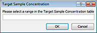
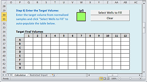
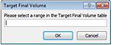
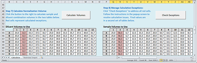
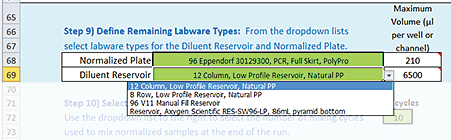
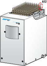
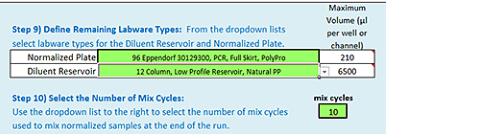
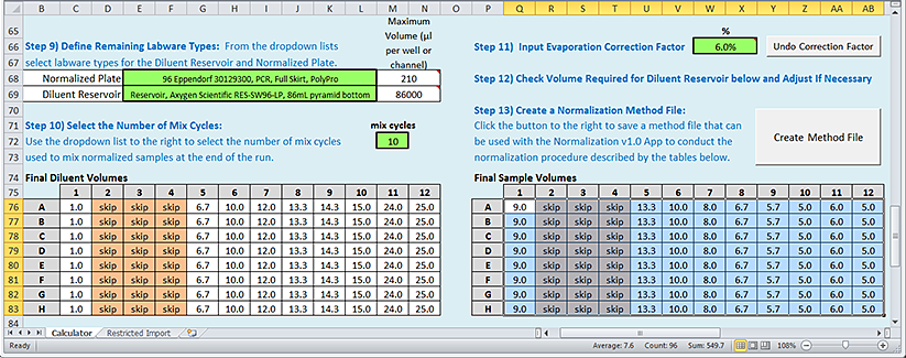
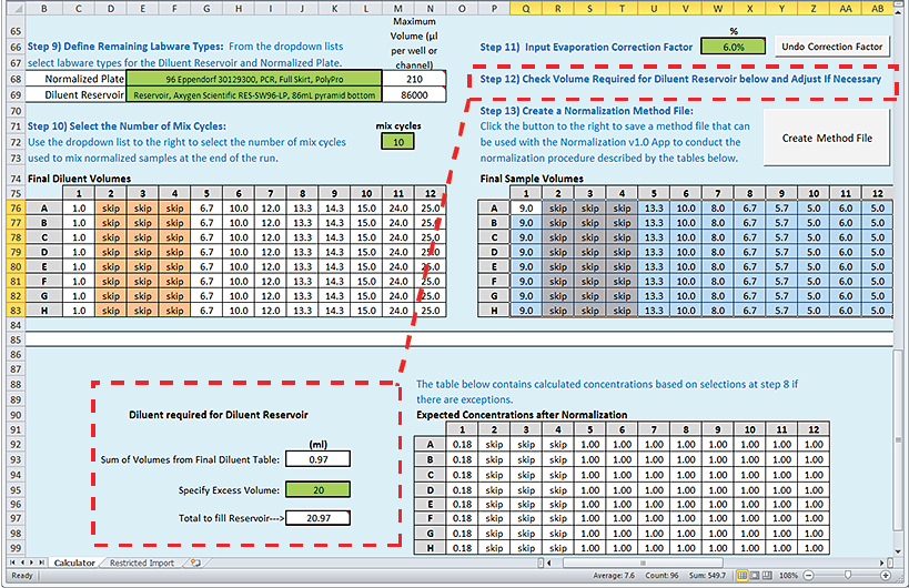
Figure. Normalization Method Setup Tool
 
The Method Setup Tool steps you through the process of defining a normalization method and creating a method file. The method file contains all the required information for the Normalization protocol on the AssayMAP Bravo Platform. The file is a record of the intended normalization process.
Before you start
Ensure that you have a Microsoft Excel file or a delimited text file (.csv or .txt) that contains the sample concentration values to be imported. The file should contain an 8‑by‑12 array of values, where
Figure. Example of an Excel file with an 8-by-12 grid numbers
 
Figure. Example of a csv file with an 8-by-12 grid numbers
 
Opening the Normalization Method Setup Tool v2.0
To open the Normalization Method Setup Tool:
1
Open the Utility Library. See Accessing a utility.
2
Locate the Normalization banner, and then click Method Setup Tool.
 
Microsoft Excel starts and displays the Method Setup Tool.
 
*In Microsoft Excel, ensure that you enable content.
 
The Method Setup Tool has 13 distinct steps, which are categorized as follows:
 
 
Return to top
Defining the initial Sample plate
     Step 1) Import Concentrations
To import the values for the known concentrations in your Sample plate, use one of the following procedures:
Note: Empty cells or cells with a value of 0 are acceptable.
Importing values from an Excel file
To import the values from an Excel file (.xls or .xlsx):
1
2
Click Import Sample Concentrations. The Import Initial Sample Concentrations dialog box opens.
 
3
Click Import concentrations from an Excel file (.xls or .xlsx).
4
In the Open Excel File dialog box, select the file, and then click Open.
The selected Excel file opens and the Select Data dialog box opens.
5
Note: When selecting data from an Excel sheet, the selected range must be an 8-row by 12-column array of values that correspond to the well positions of the samples.
 
The Excel file closes and the imported values appear in the Initial Sample Concentrations area.
 
 
Importing values from a text file
To import the values from a text file (.csv or .txt):
1
Click Import Sample Concentrations. The Import Initial Sample Concentrations dialog box opens.
 
2
Click Import concentrations from a text file (.csv or .txt).
3
In the Import Text File dialog box, select the file and click Import.
4
In the Excel Text Import Wizard that appears, follow the instructions to specify the type of delimited file.
 
5
In the Import Data dialog box, select Existing worksheet, and then click OK.
 
The content of the imported file appears in the Restricted Import worksheet of the Method Setup Tool, and the Select Data dialog box opens.
 
6
The selected values appear in the Initial Sample Concentrations area.
 
 
Return to top
     Step 2) Define Concentration Units
To define the concentration units:
In the green box next to Step 2) Define Concentration Units, verify that the unit of measure for the sample concentration is correct. If necessary, type the correct units.
 
This input is only a reminder. It has no impact on the subsequent data or volume calculations.
 
*Ensure this unit of measure is constant throughout the setup process. The tool does not adjust calculations to accommodate the use of different units for the initial and target concentrations.
 
 
Return to top
     Step 3) Select Initial Sample Plate
To select the initial Sample plate:
1
Click the Sample Plate box, and then select the labware from the list.
 
2
Notice the value that automatically appears in the Unusable Volume box. To calculate the usable volume, the calculator will subtract this value from the value in Step 4) Initial Sample Volume.
The unusable volume (also known as dead volume) is the volume that cannot be reliably aspirated from the microplate well due to pipetting limitations that arise from differences in well-bottom geometry.
The default value for Unusable Volume is a recommended setting that is based on extensive testing with the labware. If necessary, you may change the value, for example if the value is not appropriate for the sample liquid.
 
*A small volume excess is required in all labware types to ensure proper volume transfer.
 
For a list of recommended values for each allowable labware type, see Labware.
Note: The Labware Reference Guide also presents labware-specific pipetting overage and maximum well capacity. You can find this guide in the Literature Library page of the Protein Sample Prep Workbench.
 
Return to top
     Step 4) Enter Initial Sample Volume
Use the following procedure to define a volume of sample that is initially present in each well of the Sample plate.
To enter the initial Sample volume:
1
In the green (µL) box, type the initial sample volume.
2
Click Select Wells to Fill.
 
3
When the Initial Sample Volume dialog box opens:
a
Select the array of wells to be filled in the Usable Sample Volumes plate grid of the worksheet.
b
Click OK in the Initial Sample Volume dialog box to populate the selected wells of the plate grid.
 
Note: The values that populate the plate grid represent the volume of the Initial Sample Volume that is usable. This value is the difference between the value you entered in the green box for Initial Sample Volume and the value in the Step 3) Unusable Volume box.
If you want to clear all values from the Usable Sample Volumes plate grid, click Clear.
4
Repeat step 1 to step 3 until you have specified the volume for all the wells in the Sample plate that contain a sample.
 
Return to top
Defining the normalization targets
     Step 5) Enter the Target Concentrations
 
*Make sure you consider what is possible given the Initial Sample Concentrations and Usable Sample Volumes from Step 1) and Step 4), respectively. Although you may enter values that are not possible or practical given the Initial Sample Concentration and Usable Sample Volume, the tool will flag such values as exceptions when calculating the normalization volumes. You will specify how to handle each exception in a subsequent step.
 
Use the following procedure to specify the desired concentrations after the samples are normalized.
To enter the target concentrations:
1
2
Click Select Wells to Fill.
 
3
When the Target Sample Concentration dialog box opens:
 
a
Select the array of wells to be filled in the Target Sample Concentrations plate grid of the worksheet.
b
Click OK in the Target Sample Concentration dialog box to populate the selected wells of the plate grid.
Note: If you want to clear all values from the Target Sample Concentrations plate grid, click Clear.
4
Repeat step 1 to step 3 until you have specified the concentrations for all the wells.
 
Return to top
     Step 6) Enter the Target Volume
 
*Make sure you consider what is possible given the previous entries. Although you may enter values that are not possible or practical given the Initial Sample Concentration, Usable Sample Volume, or Target Concentration, the tool will flag such values as exceptions when calculating the normalization volumes. You will specify how to handle each exception in a subsequent step.
 
Use the following procedure to specify the desired volumes after the samples are normalized.
To enter the target volume:
1
In the green (µL) box, type a value that you want to apply to multiple wells of the microplate.
2
Click Select Wells to Fill.
 
3
When the Target Final Volume dialog box appears:
 
a
Select the array of wells to be filled in the Target Final Volumes plate grid of the worksheet.
b
Click OK in the Target Final Volume dialog box to populate the selected wells in the plate grid.
Note: If you want to clear all values from the Target Final Volumes plate grid, click Clear.
4
Repeat step 1 to step 3 until you have specified the volumes for all the wells.
Note: If the next step in the workflow involves an AssayMAP application, all the samples should be at the same target volume.
 
Return to top
Calculating and dealing with exceptions
     Step 7) Calculate Normalization Volumes
To calculate the normalization volumes:
Click Calculate Volumes. An algorithm uses the information provided in the previous steps to calculate the sample and diluent volumes required to achieve the specified normalization targets. The calculated volumes (µL) are displayed in the following areas:
 
Any wells with red highlights are considered exceptions, for which the calculated sample or diluent volume values cannot be achieved because the volumes required are either larger than the volumes available in the Sample plate or smaller than practical for the AssayMAP Bravo Platform to transfer with high accuracy.
 
Return to top
     Step 8) Manage Calculation Exceptions
 
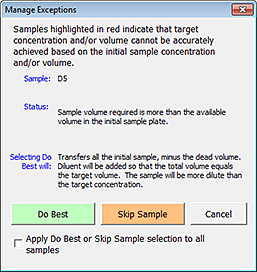
*You must click Check Exceptions in order to proceed, even if there are no red highlighted wells in the plate grid. The setup tool also performs other important conformity checks at this time.
 
In this step, you decide how to address each of the exceptions that are indicated by red highlighted wells in the plate grid.
To manage the exceptions:
1
Click Check Exceptions. The Manage Exceptions dialog box opens. The descriptions change in the Status and the Selecting Do Best Will areas depending on the conditions that caused the exception for the selected sample. The following figure shows an example.
Figure. Example of the Manage Exceptions dialog box
 
2
 
Click Do Best for each exception, sample by sample.
Select Apply Do Best or Skip Sample selection to all samples, and then click Do Best. The action is performed on all the remaining exceptions.
After addressing all the exceptions, click Close to close the dialog box.
Click Skip Sample for each exception, sample by sample.
Select Apply Do Best or Skip Sample selection to all samples, and then click Skip Sample. The action is performed on all the remaining exceptions.
After addressing all the exceptions, click Close to close the dialog box.
Select the Apply Do Best or Skip Sample selection to all samples check box, and then click Do Best or Skip Sample, as applicable.
After addressing all the exceptions, click Close to close the dialog box.
Do Best option and types of exceptions
If you select the Do Best option, the resulting Bravo actions vary depending on the conditions that caused the exception. The following four conditions cause exceptions:
1
2
3
4
The following table describes the status messages and Do Best behaviors for each of the four exceptions.
 
The AssayMAP Bravo Platform will attempt to perform the normalization as defined, by pipetting less than 5 µL of sample.
As the exceptions are managed:
 
*If you have exceptions, make sure you review the Expected Concentrations after Normalization values at the bottom of the worksheet before you create the method file.
 
 
Return to top
Finalizing the normalization method setup
     Step 9) Define Remaining Labware Types
To specify labware for the remaining deck locations:
1
Click the Normalized Plate green box, and then select the labware from the list.
Note: This plate will be placed on a Bravo Plate Riser at deck location 6, which is where the final normalized samples will be at the end of the run.
 
2
Notice the value that automatically displays in the Maximum Volume (µL per well or channel) box.
 
*If this value has a red highlight, the selected labware cannot accommodate the volume specified in Step 6) Target Volume.
 
3
Click the Diluent Reservoir green box, and then select the labware from the list.
Note: This reservoir will be placed at deck location 4 without a Bravo Plate Riser. The reservoir will supply diluent for the normalization process.
4
Notice the corresponding value in the Maximum Volume (µL per well or channel) box. This value minus the dead volume associated with the selected plate type is the volume that the Bravo 96AM Head can access in the selected labware. The Bravo 96AM Head uses a single pipette tip mounted on probe A12 to aspirate the volume.
For example, in a 12‑column reservoir, the accessible volume is only the rightmost column, and in an 8‑row reservoir, the accessible volume is only the topmost row.
Figure. Upside down view of Bravo 96AM Head showing probe A12
 
 
Return to top
     Step 10) Select the Number of Mix Cycles
In this step you select the number of mix cycles to perform after all the samples and diluent are added in the Normalized plate. The Bravo 96AM Head presses on the full selection of used pipette tips from deck location 3, and then mixes all the wells at the same time.
The mixing volume is 75% of the cumulative plate volume, up to the maximum capacity of the pipetting method, where
Capacity for 250 µL pipette tips = 140 µL
Normalization methods for large volumes may require a greater number of mix cycles, which you should determine empirically.
To select the number of mix cycles:
Click the mix cycles box, and then select the value from the list.
 
 
Return to top
     Step 11) Input Evaporation Correction Factor
In general, a Normalization protocol run of 96 samples on the AssayMAP Bravo Platform requires approximately 110 minutes. During this time, the samples can evaporate, especially by the time the 96th sample is transferred. The optional Evaporation Correction Factor helps to compensate for the sample evaporation.
The evaporation rate will vary depending on the sample solution. You should empirically determine the correction factor using test samples. See Assay development guidelines for a detailed explanation of when to use this factor and how to calculate an appropriate value to use.
To account for sample evaporation:
1
The tool automatically adjusts the values in the Final Diluent Volumes and Final Sample Volumes plate grids. The button label changes to Undo Correction Factor.
Note: If you want to undo the change, click Undo Correction Factor.
 
Return to top
     Step 12) Check Volume Required for Diluent Reservoir below and Adjust If Necessary
 
*A small volume excess is required in all labware types to ensure proper volume transfer.
 
To verify that the Diluent reservoir has sufficient volume:
1
Review the Diluent required for Diluent Reservoir area at the bottom of the worksheet. The Method Setup Tool calculates the total fill volume for the Diluent reservoir based on the calculated Final Diluent Volumes and the recommended excess volume for the selected labware type.
Note: For a list of recommended values for each allowable labware type, see Labware.
2
If a red highlight appears on the Total to fill Reservoir value, the diluent volume required is more than the selected labware can hold. In this case, select a different labware option for the Diluent Reservoir in Step 9).
Note: If you are using a 12-column reservoir or an 8-row reservoir, the Total to fill Reservoir value represents the volume in the rightmost column or topmost row, respectively.
3
Make a note of the Total to fill Reservoir volume. You will use this value to prepare the diluent reservoir for the normalization run.
 
 
Return to top
     Step 13) Create a Normalization Method File
To create the method file to use for the protocol:
1
Click Create Method File.
2
In the Save As dialog box, specify the file name and the storage location, and then click Save.
The file is saved as a comma-separated value (.csv) text file. The default method file storage location is in the following folder:
… /VWorks Workspace/Methods/AM Normalization Utility v2.0
3
To close the Normalization Method Setup Tool:
a
Click File > Close or exit the Microsoft Excel software. A Microsoft Excel dialog box opens and asks if you want to save the changes.
b
Note: If you manually type the values into the plate grids of the Normalization Method Setup Tool, you may have unexpected results.
 
Return to top