|
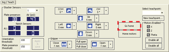
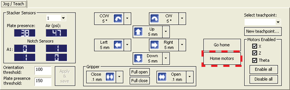
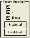
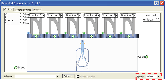
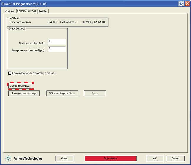
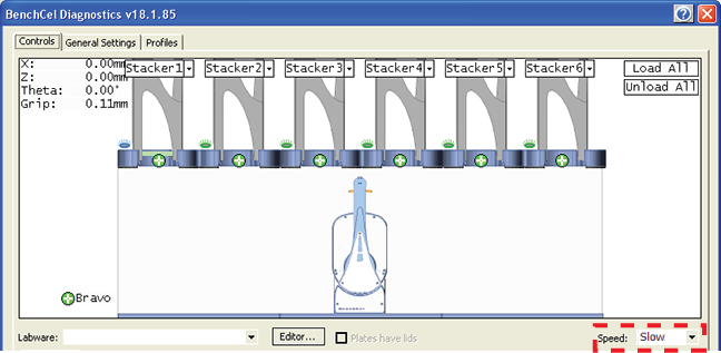
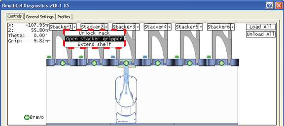
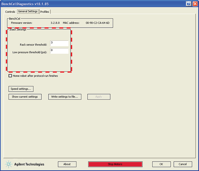
The BenchCel Diagnostics software has three tabbed pages: Controls, General Settings, and Profile. You use the commands and parameters available in the Controls and General Settings tabs when troubleshooting problems.See Quick reference for the complete list of available commands.The home position is where the robot head is at the center of the BenchCel Microplate Handler and the robot arms are perpendicular to the x-axis. You send the robot to the home position if you want the robot out of the way in a safe position.
1
2 Click Go Home.
1
2 Click Home Motors.
1
2 In the Motors Enabled area, select or click the following:
Select the option to enable the theta-axis motor. Clear the check box to disable the theta-axis motor.
1
Jogs the robot arm counterclockwise from the current position by the specified theta-axis increment. Jogs the robot arm clockwise from the current position by the specified theta-axis increment. Jogs the robot head left from the current position by the specified x-axis increment. Jogs the robot head right from the current position by the specified x-axis increment. Jogs the robot head up from the current position by the specified z-axis increment. Jogs the robot head down from the current position by the specified z-axis increment. The speed you select in BenchCel Diagnostics applies only to the robot commands in BenchCel Diagnostics (Jog, Move, Transfer, and so on). If the robot is holding a microplate, the slower of the following will be applied: the speed you selected in the Labware Editor or the speed you selected in BenchCel Diagnostics.You can adjust the speed setting for the x‑axis, z‑axis, and theta-axis for each speed (high, medium, or slow) as a percentage of the factory-set maximum speed.
1
2
Note: During a protocol run, the robot uses the speed selection in the VWorks Tools > Options dialog box. If the robot is holding a microplate, the slower of the following will be applied: the speed in the Labware Editor or the speed in the Tools > Options dialog box. For more information, see the VWorks Automation Control User Guide.
1
2 In the Speed Settings dialog box, type the percentage of the factory-set maximum speed for the axis speed setting.
Note: The speed settings apply to the speeds you select in BenchCel Diagnostics, Labware Editor, and the VWorks Options dialog box.
3 Click OK to save the changes.
2
3 In the graphical display area, click the plus sign (
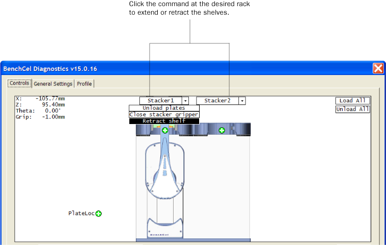
) at either of the following:
To transfer a microplate from a stack, you must first click Load Stacker. During the transfer, the robot downloads the plate, places it at the other selected teachpoint, and then backs into the safe zone. Lidded labware only. Removes the lid from the labware that is at the selected teachpoint. Lidded labware only. Replaces the lid on the labware that is at the selected teachpoint.The clamps close and open the stacker grippers automatically during the loading, unloading, downstacking, and stacking procedures. When diagnosing problems or after an aborted run, you can use the commands in BenchCel Diagnostics to open or close the clamps (stacker grippers). For example, you might want to open the clamps (stacker grippers) to remove a microplate.
1
2 In the graphical display area at the top of the rack, click Stacker, and then choose Open stacker grippers or Close stacker grippers. A click sounds as the clamps (stacker grippers) open or close.
The shelves extend and retract automatically during the downstacking and upstacking processes. When diagnosing problems or after an aborted run, you can use the commands in BenchCel Diagnostics to extend or retract the shelves.
1
2 In the graphical display area at the top of the desired rack, click Stacker, and then choose Extend Shelves or Retract Shelves. A click sounds as the shelves extend or retract.
When testing new or troubleshooting existing labware definitions, you can use BenchCel Diagnostics to make changes to some of the labware parameters without opening Labware Editor. For example, you can change the stacking thickness, gripper offsets, notch specification, and lid specifications.Note: Changes you make to the labware parameters in BenchCel Diagnostics are also updated in the Labware Editor.
1
2 Click the Labware tab and make your changes to the labware parameters.
•
3 If you want to check for notches, under Notch Locations, select Check Orientation, and then select one or more of the microplate corners to indicate the notch location.
a
b
c In the Lidded Plate Parameters (mm) area, type the following values after you verify the measurements. For details on measuring these parameters, see BenchCel Diagnostics - Labware tab.
5 To make changes to other labware parameters, click Editor. You can make changes in the Labware Editor. See the VWorks Automation Control Setup Guide for instructions on using the Labware Editor.
6 Click Apply and save labware parameters.
CAUTION The changes are stored in the BenchCel flash memory. The changes you make to the general settings will take affect any time you are using this BenchCel device regardless of profile, protocol file, or device file.
1
2 In the Stack Settings area, type a new value for the parameter you want to change.
3 Select Home robot after protocol run finishes if you want the robot to return to its home position after the protocol run is finished.IMPORTANT Home robot after protocol run finishes applies to all BenchCel devices that are controlled by the same computer running the VWorks software.
4
5 Click OK to apply and save the new setting values.
How to open BenchCel Diagnostics