|
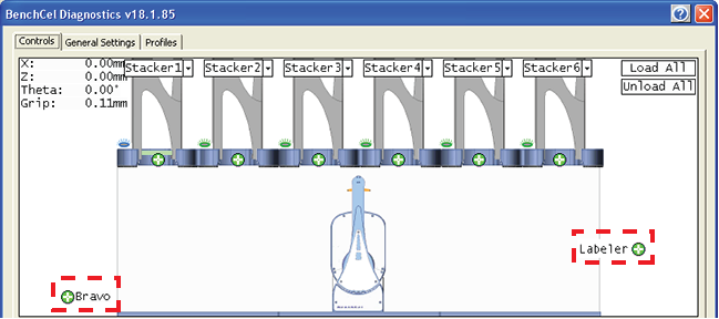
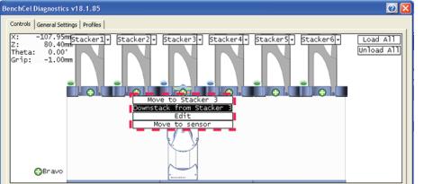
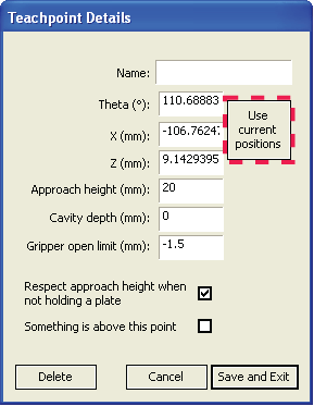
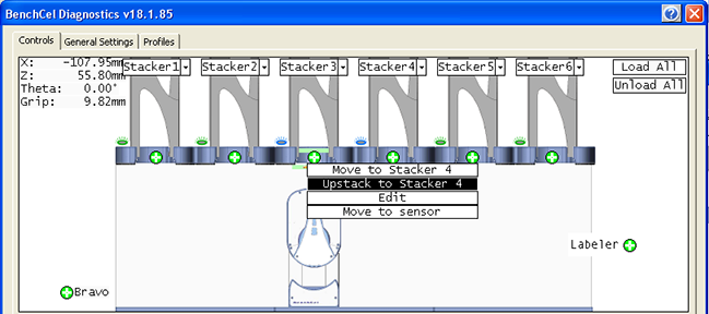
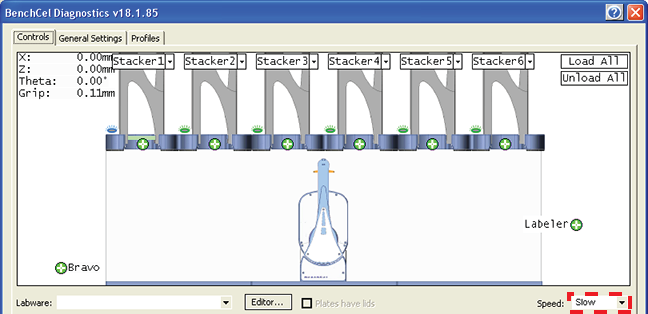
A teachpoint is a set of coordinates that define where the robot can pick up or place labware. The location can be on an external device or a platepad. You set, edit, and save teachpoints in BenchCel Diagnostics. The teachpoints are displayed as plus signs () in the graphical display area in the BenchCel Diagnostics dialog box.
Note: The graphical display area also shows teachpoints () at the stacks. These teachpoints are preset at the factory and should not be changed.
You must use one teachpoint file for each BenchCel device. If you integrate a new device with the BenchCel Microplate Handler, you can add the new teachpoints to the existing file. If you have multiple BenchCel devices in a workstation, you must create a teachpoint file for each BenchCel device in the workstation.The teachpoint file is referenced by a profile. For information about profiles, see Creating profiles.
• The labware you want to use is defined (VWorks Automation Control Setup Guide).
1 Place two or three spare microplates in a labware rack, and then install the rack on the BenchCel Microplate Handler. For instructions, see Filling and emptying the labware racks and Installing and uninstalling the labware racks.
2
3 On the Profiles page, look in the Teachpoint File area to make sure the correct teachpoint file is loaded. You will be adding new teachpoints to this file.
4
5 In the graphical display area, click Stacker at the top of the rack that contains the spare microplates. In the menu that appears, click Load plates. The BenchCel device moves the stack down and holds the stack in the stacker grippers, or supports the stack on the stacker shelf, as specified in the labware definition.
6 In the graphical display area, click the plus sign () at the stacker head that contains the spare microplates. In the menu that appears, click Downstack from Stacker. The robot head moves under the stacker and holds the first spare microplate in its grippers.
7
8 Click Go Home. The robot head moves to its home position at the center of the BenchCel Microplate Handler.
9 In the Motors Enabled area, clear the check boxes for X and Theta to disable the x‑axis and theta‑axis motors. The z‑axis motor is still enabled (the Z box is selected).
• Visually inspect the position of the microplate relative to the plate stage. If the robot is not aligned with the plate stage along the y-axis (front-to-back direction), move the robot into the safe zone, physically slide the external device and its integration plate along the y-axis, move the robot back and see if the robot arms are aligned with the plate stage. You might have to loosen the clamp screw to slide the device (see About integrating devices in a workstation).
• To move the robot head up or down in small, precise increments, open BenchCel Diagnostics. On the Controls page Jog/Teach tab, select the jog increment from the corresponding list, and then click Up () or Down (
).
• With the x-axis and theta-axis motors disabled, gently push or pull the robot side to side so that the robot arms are able to place the microplate on the plate stage.
12 Visually inspect the position of the microplate on the target location. It should be centered on the location. If it is not, ensure that the x-axis and theta-axis motors are disabled on the Jog/Teach tab, and then manually move the robot head to the microplate at the location.
1 Tighten the BenchCel integration plate clamp screw using the 3-mm hex wrench.
To record the teachpoint coordinates in BenchCel Diagnostics:
2
3 In the Teachpoint Details dialog box, click Use current positions. The robot’s current coordinates fill the Theta, X, and Z boxes.
The vertical distance (mm) from the home or lowest z‑axis position. A positive value moves the robot head up from the home position. A negative value moves the head down from the home position. The range of movement is from ‑1.5 mm to 104 mm.IMPORTANT Ensure the Z value is greater than ‑1.5 mm. If it is not, jog the z-axis up to obtain a value that is larger. Otherwise, the software will issue a z-position out-of-bounds error if a plate with a smaller Robot gripper offset is used.
Type a one-word name for the teachpoint. For example, if the teachpoint is on an integrated Microplate Labeler, you might want to name the teachpoint Labeler.This name appears in the graphical display area in the BenchCel Diagnostics dialog box. You can start with an approach height of 20 mm (default). However, if there is an obstruction above the teachpoint, a smaller approach height might be required to prevent a collision.Note: This value applies when the robot is holding a microplate. When it is not holding a microplate, the robot will approach the teachpoint at the height of the teachpoint, unless you select the Respect approach height when not holding a plate option. This setting is not commonly used and should be set at 0 mm for most applications.For example, suppose the Robot gripper offset is 5 mm and the platepad you want to use has depth of 9 mm. When the microplate sits in the platepad, the robot grippers cannot reach the offset height, as the following diagram shows. To account for this depth, you can set the Cavity depth at –9 mm. The robot grippers will grip the microplate 9 mm above the 5 mm offset (at 14 mm). Type the maximum distance (mm) the robot grippers are allowed to open as they prepare to grip the microplate at the teachpoint. The maximum value you set is less than or equal to the Robot Gripper Open Position value set in the BenchCel Diagnostics Controls Labware tab.Use this setting if the teachpoint area is narrower than the robot grippers open position. (To see this value, click Save and exit, and then click the Labware tab in the BenchCel Diagnostics Control tab.)Note: This value is used only at the teachpoint and not during other operations. Select the option to limit the robot’s movements within the robot safe zone. With this selection, the robot will move only along the theta-axis as long as all of its parts (head, arms, grippers, and labware) are within the safe zone when approaching or moving away from the teachpoint.Clear the check box to allow the robot to use the full workspace. The robot’s theta-axis movements are not limited when approaching and moving away from the teachpoint.Use this option to limit the robot’s movements to prevent collision when approaching a teachpoint. For example, when moving labware to and from a multi-shelf device such as the Vertical Pipetting Station, this option prevents the robot from colliding with the shelf above the target teachpoint.
5 Click Save and Exit to save the teachpoint in the teachpoint file and close the Teachpoint Details dialog box.On the Controls page in BenchCel Diagnostics, the new teachpoint appears in the graphical display area as a plus sign ().
7 On the Jog/Teach tab, click Go Home. The software prompts you to enable all the motors. After the motors are enabled, the robot head moves to the center of the BenchCel device, and the robot arms are perpendicular to the x-axis. The robot grippers are still holding the spare microplate you used to set the teachpoint.
8 On the Controls page, click the plus sign () of the stacker that is holding the spare microplates, and then choose Upstack to Stacker. The robot moves the microplate back into the stack.
1
2 In BenchCel Diagnostics, click the Controls tab, and select the desired labware definition from the Labware list.
3 In the graphical display area, click the plus sign () at both of the following locations:
4 Note: You can set the Slow speed as a percentage of the factory-set maximum speed. To do this, see Changing the robot speed.
5 In the graphical display area, click the stacker that contains the spare microplates. In the command menu that appears, click Transfer to <teachpoint name>, where <teachpoint name> is the name of the teachpoint you are verifying. The robot picks up the first microplate in the stack and moves it to the selected teachpoint.
• If the robot did not move the microplate to the correct location, proceed to Editing existing teachpoints to refine the teachpoint.In the graphical display area, click the plus sign () at the new teachpoint, and then choose Transfer to Stack. The robot moves the microplate from the teachpoint back to the stack.
• Move the BenchCel Microplate Handler
1 In BenchCel Diagnostics, click the Profiles tab, and verify that the correct teachpoint file is loaded.
2 Click the Controls tab. In the graphical display area, double-click the plus sign () of the teachpoint you want to edit.
• Follow the instructions in Determining the teachpoint coordinates to manually move the robot head to a new teachpoint position and set the teachpoint.
4 Click Save and Exit to save the revised teachpoint in the teachpoint file.
1 In BenchCel Diagnostics, click the Profiles tab, and verify that the correct teachpoint file is loaded.
2 In the graphical display area, double-click the plus sign () of the teachpoint you want to delete.
3 In the Teachpoint Details dialog box, click Delete. The current teachpoint file will automatically be updated when you delete a teachpoint.