Bravo Platform User Guide : Accessories and platepads : Installing and setting up a Vacuum Filtration Station

Installing and setting up a Vacuum Filtration Station
About this topic
This topic describes how to set up the Vacuum Filtration Station on the Bravo Platform.
This topic contains the following information:
Before you start
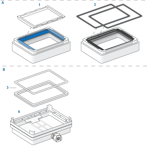
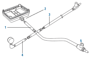
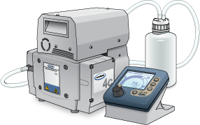
The Vacuum Filtration Station may be installed on a standard Bravo Platform and is compatible with the Series III disposable-tip heads only. Agilent Technologies recommends installing the station on a short platepad (SRT platepad). The Vacuum Filtration Station is not supported on the SRT Bravo Platform.
The following table presents the workflow for setting up and automating the assembly and disassembly processes for the Vacuum Filtration Station.
 
Determine which components of the Vacuum Filtration Station are required for your labware.
In Diagnostics, configure the Vacuum Filtration Station in the device profile.
In the VWorks Labware Editor, ensure that the labware definitions are correct for the filter and collection plates that will be placed on the Vacuum Filtration Station during a protocol run.
Set the microplate parameters and the Bravo gripper offset for the labware.
In the VWorks software, add one or more pairs of the vacuum assembly and disassembly tasks in the protocol.
Component descriptions and options
 
 
The Vacuum Filtration Station applies vacuum to filter the contents of microplates placed on the station. The station consists of a collar and a manifold base that can be assembled and disassembled automatically. The following figure shows the primary components.
Figure. Vacuum Filtration Station components: A collar options, B base and optional inserts
 
 
The same collar as item 1, except the flexible blue gasket is replaced with two black gaskets that are held in place by an adhesive. One black gasket adheres to the top of the collar, and the second black gasket adheres to the underside surface of the collar top to maintain the correct spacing underneath the collar.
For more details about the Vacuum Filtration Station collar and base, see the Millipore user documentation.
 
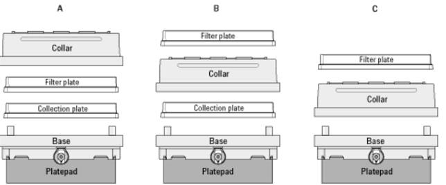
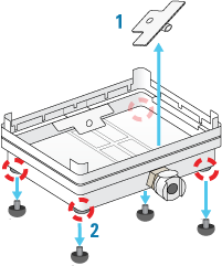
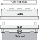
*Ensure that the base of the station is installed on a short platepad (SRT platepad). If the Vacuum Filtration Station configuration is too tall for the Bravo gripper to assemble without the risk of a collision, an error will occur during the run.
 
Supported stacking configurations
In addition to the basic configuration of the collar stacked on the station base, other configurations can be automatically assembled and disassembled during a protocol run. The common configuration options are as follows:
Configuration A. The filter and collection plates are part of the station assembly.
Note: Double-filtration is possible in configuration A by including one filter plate as part of the station assembly and a second filter plate on top of the vacuum collar.
Configuration B. The filter plate is not part of the station assembly. The robot will move the filter plate to the station during the protocol run after the assembly process is finished.
Configuration C. The filter plate is not part of the station assembly. The robot will move the filter plate to the station during the protocol run after the assembly process is finished.


Installing the station
Before you start
 
*To avoid potential injury and damage to the device, turn off the device before installing or removing an accessory.
 
 
*An SRT platepad is typically required to provide clearance for the height of the assembled vacuum stack.
 
Make sure you have the following:
Vacuum Filtration Station kit. Contains the vacuum manifold base and collar, tubing for robotic and manual setups, waste bottle, and filter.
 
*The house vacuum must be regulated to a maximum of 286.49 mbar (8.46 inHg), because the pinch-valve tubing will collapse with higher vacuum pressure.
 
For detailed information, see the ME4C NT VARIO Pump manual at https://www.vacuubrand.com.
 
*Inspect the Vacuum Filtration Station base to ensure that it is ready for robotic use: (1) Remove the plug, if present, that blocks the vacuum port from within the base. (2) Unscrew the four rubber feet if installed on the base.
 
Figure. Removal of (1) plastic plug from vacuum port and (2) rubber feet from base
 
Determining the installation location
Make sure that the installation location for the Vacuum Filtration Station base enables routing of the tubing.
For example, on the Bravo deck, you can install the Vacuum Filtration Station on a platepad at deck location 1, 2, or 3 if you want to route the tubing out the rear opening.
Figure. Installation options on the Bravo deck: location 1, 2, or 3 on the back row
 
Installing the station
To install a Vacuum Filtration Station:
1
Place the base of the Vacuum Filtration Station on the platepad (typically, an SRT platepad).
Ensure that the base sits level and that the vacuum port faces in the correct orientation for the tubing exit.
2
3
Connect the Vacuum Filtration Station as required for the type of vacuum source:
Connecting to house vacuum with the pinch-valve module
Perform the following tasks to connect the pinch-valve module to the house vacuum source.
 
Connecting the control-valve-and-gauge assembly
Refer to the following figure to connect the manual pressure control-valve-and-gauge assembly.
 
To connect the pressure control-valve-and-gauge assembly:
1
Ensure that the base (manifold) of the Vacuum Filtration Station is installed on the Bravo platepad.
2
Connect the coupling insert on the end of the four-way connector (1) to the quick-disconnect fitting (2) on the base. Push the coupling insert until it clicks.
3
Connect the coupling insert on the end of the manual vacuum control valve tubing (3) to the quick-disconnect fitting on the short arm of the four-way connector.
4
Connect the coupling insert on the end of the vacuum pressure gauge tubing (4) to the quick-disconnect fitting on the long arm of the four-way connector.
5
Optional. Disconnect the manual on/off toggle switch (5) from the end of the tubing. This toggle switch is not required for the setup.
Connecting the pinch valve tubing
 
*The house vacuum must be regulated to a maximum of 286.49 mbar (8.46 inHg), because the pinch-valve tubing will collapse with higher vacuum pressure.
 
Note: The pinch-valve tubing can collapse with regular use over time, resulting in inadequate vacuum flow for the Vacuum Filtration Station. Replace the tubing periodically to keep the Vacuum Filtration Station functioning as intended.
The following figure shows the connections from the Vacuum Filtration Station to a vacuum source via a pinch-valve module.
Figure. Vacuum Filtration Station connections for a pinch-valve module
 
 
Branches the tubing from the Vacuum Filtration Station base to the vent and valve ports on the pinch-valve module.
Routes the tubing from the vacuum source to the Vacuum Filtration Station through the waste bottle.
To connect the Vacuum Filtration Station using the pinch-valve module:
1
2
Connect the tubing from the vacuum control valve-and-gauge assembly (1) to the open three-way connector tubing on the pinch-valve module assembly (2).
 
*If you are installing the control valve-and-gauge assembly with the optional on/off toggle switch, ensure that the toggle switch is in the on position (handle in line with valve body), as the following figure shows.
 
 
Note: The remaining tubing from the three-way connector is pre-assembled: One tube connects to the vent port, and the second tube connects through the valve port.
3
4
5
6
Connect the power cable (6) from the pinch-valve module to an AC outlet.
7
Connect the communications cable (7) from the pinch-valve module to a com port on the controlling computer.
Setting the vacuum pressure
To set the regulated vacuum pressure for the pinch valve:
1
 
2
 
3
4
 
If the vacuum pressure exceeds 8.46 inHg, the pinch valve tubing may collapse. If this occurs, turn off the vacuum source to the pinch valve and turn the control-valve knob counterclockwise to eliminate the vacuum pressure. You may need to massage the tubing slightly to open it up again.
Now you are ready to configure the Vacuum Filtration Station in the software. See Configuring the Vacuum Filtration Station in Bravo Diagnostics.
Connecting and configuring the Agilent VARIO Vacuum Pump
The following figure shows the Agilent ME4C NT VARIO Vacuum Pump.
Figure. Agilent ME4C NT VARIO Vacuum Pump
 
For detailed instructions about the VARIO pump, see the manufacturer’s Instructions for use, provided with the pump.
The following figure shows the connections for a Vacuum Filtration Station that uses the ME4C NT VARIO Vacuum Pump.
Figure. Vacuum Filtration Station connections for ME4C NT VARIO Vacuum Pump
 
 
To connect the Vacuum Filtration Station to the ME4C NT VARIO Vacuum Pump:
1
Make sure the Vacuum Filtration Station base is installed on the platepad.
2
a
Connect the tubing with the quick-disconnect fitting to the port on the station base (1), and connect the other end to the three-way connector (2).
b
c
3
Connect the output tubing from the waste bottle (3) to the filter (4), and connect the output tubing from the filter to the inlet on the front of the pump (6).
4
Carefully, connect the pump’s power supply cable (7) to the 4-pin connector on the back of the controller (5).
 
*Do not try to force the cable connector into the port on the controller. Doing so can damage the connector.
 
5
Connect the communications cable (8) from the pump controller to a com port on the controlling computer.
6
Connect the power cord (9) from the pump to an AC outlet.
7
8
9
10
Configure the com port for the Vacuum Filtration Station and other settings in Bravo Diagnostics. For instructions, see Configuring the Vacuum Filtration Station in Bravo Diagnostics.
To configure the controller communication settings for the pump:
1
At the controller panel, locate the power button (1) and the selection knob (2), as the following figure shows.
 
 
*In the following steps, the display will reset after 20 seconds of inactivity. If this happens, repeat the steps to access the configuration display and make the selections.
 
2
Note: The controller display will turn on automatically if the controller power button was already set to on.
3
a
b
In the Configuration display, turn the knob to move the selector to RS‑232, and then press the knob to make the selection.
c
In the RS-232 configuration display, ensure that the parameters are set as follows:
 
Note: Later, after you initialize the Vacuum Filtration Station in your automation software, the Remote setting will change to On automatically.
To change a value, turn the selection knob to the desired parameter, press the knob to access the value, and then turn the knob to change the value. Press the knob again to confirm the new setting.
d
Use the selection knob to move the selection to Back, and press the knob to exit each display until you exit the Configuration display.
4
The PC icon 
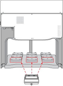
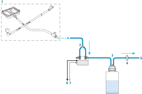
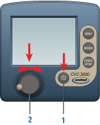
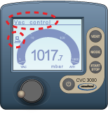
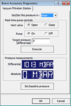
will appear after you initialize the Vacuum Filtration Station in your automation software, indicating that the pump is under remote control.
 
 
*Before using the VARIO pump, refer to the safety information in the manufacturer’s user documentation.
 
Note: While the PC icon appears on the controller display, the Vacuum Filtration Station is under the control of the computer, and you can no longer control the pump locally using the controller display.
If you want to reset the controller, press the power button to turn it off, set the power switch on the back of the pump to off. Wait a minute, and then turn on the pump and turn on the controller again.
For additional information on the VARIO pump, see the manufacturer’s user documentation.
Uninstalling the Vacuum Filtration Station
 
*To avoid potential injury and damage to the device, turn off the device before installing or removing an accessory.
 
To uninstall the station:
1
2
3
4
Disconnect the tube from the Vacuum Filtration Station.
5
6
Remove the Vacuum Filtration Station from the platepad.
Configuring the Vacuum Filtration Station in Bravo Diagnostics
To configure the Vacuum Filtration Station:
1
In Bravo Diagnostics, click the Profiles tab, and verify that the correct profile is initialized.
2
Click the Configuration tab.
3
In the Locations list, select the deck location of the Vacuum Filtration Station base.
4
In the Location is configured as list, select Accessory. The Accessories Wizard opens.
5
In the Location list, confirm the deck location of the Vacuum Filtration Station base, and then click Next.
6
In the Accessory list, select Vacuum Filtration Station, and then click Next.
7
In the “Vacuum Filtration Station” properties table, set the following:
a
Serial Port. The com port on the controlling computer to which the communications cable from the pinch-valve module or the pump connects.
b
Select one of the Configuration options:
Always assembled. The station consists only of the base and the collar, or the robot will not assemble or disassemble the station components during a protocol run. If you select Always assembled, select the Collar type. The options are Standard (38 mm) or Deep (67.5 mm).
Start disassembled. The station components are at different deck locations and you want to use the Assemble Vacuum and Disassemble Vacuum tasks during a protocol run.
c
Pump connected. Choose one of the following:
 
If you select ME4CVario, set the Pump Pressure Units to match the unit setting on the VARIO pump controller. The options are mbar, Torr, and hPa.
Click Next.
8
Starts disassembled configuration only. Select the following:
a
In the Location for Vacuum Filtration Collar list, select the deck location at which the collar is located, and then click Next.
b
In the Vacuum Filtration Collar properties table, specify the following, and then click Next.
 
9
Click Finish.
Note: If you verified the accuracy of the platepad teachpoint before installing and configuring the Vacuum Filtration Station, no further adjustment to the teachpoint should be required.
10
In the Profiles tab, click Update this profile.
Testing the Vacuum Filtration Station
Before you start, ensure that you initialize the correct profile in Bravo Diagnostics.
Testing the Pump Standard option
If you selected the Standard connection option when configuring the Vacuum Filtration Station, use the following procedure to test the vacuum supply to the station.
To test the Standard connection for a Vacuum Filtration Station:
1
Verify that the pre-assembled Vacuum Filtration Station is in place on the target deck location and connected via the pinch-valve module.
2
In Diagnostics, click the Configuration tab.
3
In the Accessory Configuration area, highlight Vacuum Filtration Station, and then click Diagnose accessory.
 
4
In the Accessory Diagnostics dialog box, start the vacuum as follows:
a
Set the Vent valve to Closed.
b
Set the Vacuum valve to Open.
c
Click Execute.
Figure. Accessory Diagnostics dialog box for the Standard connection
 
5
a
Set the Vent valve to Open.
b
Set the Vacuum valve to Closed.
c
Click Execute.
6
Click OK.
Configuring the ME4C NT VARIO Vacuum Pump and testing the vacuum
If you selected the ME4C Vario connection when configuring the Vacuum Filtration Station, use the following procedure to configure the pump settings and test the vacuum supply to the station.
For more details on the ME4C NT VARIO Vacuum Pump, see the manufacturer’s user guide.
To configure the ME4C NT VARIO Vacuum Pump and test the station:
1
2
In Diagnostics, click the Configuration tab.
3
In the Accessory Configuration area, highlight Vacuum Filtration Station, and then click Diagnose accessory.
 
The Accessory Diagnostics dialog box opens.
Figure. Accessory Diagnostics dialog box for the ME4C NT VARIO Vacuum Pump
 
4
a
In the Get/Set the pressure in list, select the desired unit of measure (mbar, Torr, hPa, mmHg, cmHg, and inHg). If the selected units differ from the configuration, the software will convert the values.
b
Set the Vent valve to Open.
c
Set the Pump to Off.
d
Type the Target pressure (differential).
e
Click Set baseline pressure.
5
a
Set the Vent valve to Close.
b
Set the Pump to On.
c
Set the Target pressure.
d
Click Execute.
6
a
Set the Vent valve to Open.
b
Set the Pump to Off.
c
Click Execute.
Related information
 
Creating or updating labware definitions for filter and collection plates used with the Vacuum Filtration Station, including specifying the gripper offset
Videos that show the Bravo Platform, Vacuum Filtration Station, and VWorks software