|
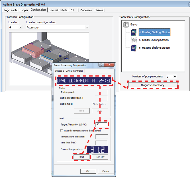
This topic describes how to configure the Bravo thermal and thermal shaking accessories that are controlled by the Inheco Single TEC Controller (STC) or Multi TEC Controller (MTC). The Inheco STC and MTC controlled accessories include the following:
Figure. Inheco STC and MTC Controllers
1
2 Click the Configuration tab.
3
4 In the Accessories Wizard, select the Location of the installed accessory. In the Choose Accessory page, select Heating Shaking Station.
a In the MTCSTC Id box, select the ID number of this device. The ID number identifies the specific device for the VWorks software.
b Select the MTCSTC Type, either STC or MTC.
c In the Slot Id box, select the slot number on the Inheco STC or MTC rear panel where the accessory’s cable is connected.
6 Click Finish.
7 When the configuration message appears, click Yes to initialize the accessory and move the teachpoint to a safe height.
8
9
2
3 In the Accessory Configuration area, select the Heating Shaking Station, and then click Diagnose accessory.
4 In the Bravo Accessory Diagnostics dialog box, verify that the correct device appears in the display at the top.
5 Shaking accessories only. Set the parameters in the Shake area:
a In the Shake speed box, type the shaking speed.
b In the Shake duration box, type the time duration (seconds).
c In the Shake type box, select the type of stirring motion.
d Click Start to test the shake parameter settings. At the device, verify that the accessory operates correctly.Click Stop to turn off the shaking feature.
6 Thermal accessories only. In the Heat area, set the parameters to test the temperature function:
a In the Target temp box, type the temperature (°C).
b To specify a time limit within which to reach the target temperature, select the Wait for temperature to be reached check box, and then set the following:
• In the Temperature tolerance box, type the ±°C.
• In the Time limit box, type a time limit (minutes).
c Click Start to test the Heat parameter settings. At the device, verify that the accessory operates correctly.Click Turn Off to stop the heating or cooling.
7 Click OK to close the dialog box.The teaching procedure can vary depending on the combination of microplate, plate nest, and adapter. The procedures in this section are for the following configurations on a Bravo Platform with a disposable-tip head:
• Peltier Thermal Station with generic plate nest and adapterIf you have a Peltier Thermal Station with a custom plate nest and adapter, Contact Agilent Technical Support for guidance on how to teach your combination of microplate, plate nest, and adapter.
The microplate bottom surface configuration affects how it sits in the station’s plate nest. The following figure shows a skirted microplate in a Peltier Thermal Station that has a generic plate nest and adapter. In the figure, the well bottoms rest on the top of the adapter (1), and the skirt rests on the top of the plate nest’s lower surface (2).Figure. Skirted microplate sitting in Peltier Thermal Station with generic plate nest and adapter (cut-away side view)
As the figure shows, the height difference between the adapter top (1) and the plate nest top (2) enables a skirted microplate to nest in the station. The well bottoms must sit directly on the adapter top to enable an efficient temperature transfer. However, the teachpoint must account for this height difference to ensure that the Bravo robot grips the microplate at the correct position and performs pipetting tasks at the correct height.
2 Using calipers, measure the height difference between the adapter top (1) and the plate nest top (2) on all four sides of the plate nest interior. Make a note of the smallest number. Later in the procedure, you will add this value to the z-axis value for the teachpoint.Note: Alternatively, you can use a 384-well microplate instead of the teach plate to set the teachpoint xy coordinates. In this case, you set the xy coordinates based on the center of the A1 well quadrant, as the following figure shows.
4
5 In Bravo Diagnostics, click the Processes tab, select a tip box, and perform a Tips On command. For details, see Performing a task using Bravo Diagnostics.
6
a Select the deck location of the station from the Location list.
b
c Click Teach to set the teachpoint.
d
7 Adjust the teachpoint z-axis value for the teach plate height as follows:
a Jog the head up in the z‑axis so that you have enough room to remove the teach plate. Remove the teach plate.
b In the Jog/Teach tab, use the controls to jog the head down in the z‑axis until there is paper-thin clearance between the end of the tip and the top surface of the adapter.
c Click Teach to set the teachpoint.
d
8 In Bravo Diagnostics, click the Processes tab, select the empty tip box, and perform a Tips Off command. For details, see Performing a task using Bravo Diagnostics.
9 Adjust the teachpoint z-axis value for the height difference between the adapter and the plate nest as follows:
a
b
c Click Teach to set the teachpoint.
d
1
2 Select the Labware from the list.
3 In the Location A list, select a deck location.
4 In the Location B list, select the thermal station location.
• Pick A -> B to pick up the microplate from deck location A and place it on deck location B.
• Pick B -> A to pick up the microplate from deck location B and place it on deck location A.