Bravo Platform User Guide : Introduction : Hardware overview

Hardware overview
About this topic
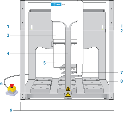
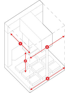
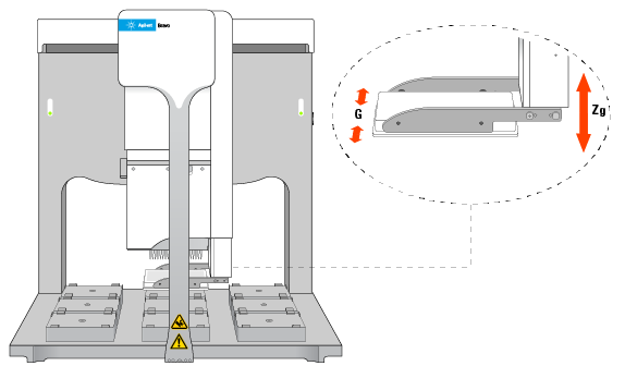
This topic describes the Bravo Platform primary hardware components and the axes of motion.
 
 
Primary hardware components
The following figure and table describe the primary Bravo hardware components.
Figure. Bravo Platform components (front view)


(solid blue). The Bravo Platform is turned on and in standby mode.
(flashing green). The software is running a protocol on the Bravo Platform.
(flashing orange). The software has initialized the Bravo Platform and Bravo Diagnostics is open.
(flashing red). The software has encountered an error while running a protocol or the interlock circuit is tripped.
The fixture that provides the mechanical connections and communication inferface for the liquid-handing head. The head mount attaches to an arm that extends from the Bravo rear wall of the tie bar. The head mount travels along the arm between the front and back of the deck (y-axis). The arm moves the head mount from side to side across the deck (x-axis). For details, see Axes of motion.
The vertical bar at the front of the device that adds structural support to the Bravo head mount. The tie bar moves at high speed from side to side (x‑axis) across the front of the Bravo deck whenever the head moves to a deck location.
The platform uses interchangeable Bravo-compatible heads, including disposable-tip heads, the Bravo 96AM Head for AssayMAP cartridges, and pin tools.
The safety equipment that reduces the risk of injury to users from Bravo moving parts. If an object disrupts the light curtain, the motion of the Bravo head stops. For details on the Bravo safety equipment, see the G5562A, G5563A Bravo Platform Safety and Installation Guide.
Axes of motion
The Bravo Platform has components that move in the x-, y-, and z-axes, as the following figure shows.
Figure. Bravo Platform primary axes of motion
 
If the Bravo Platform is fitted with a gripper, the gripper moves with the Bravo head. In addition, the gripper has the following axes of motion:
G‑axis. The opening and closing distance of the gripper fingers, which enable the gripper to grip and release labware.
Zg‑axis. The vertical distance the gripper arm moves, which enables the gripper to extend beyond the pipette head.
Figure. Bravo gripper assembly axes of motion


The motion of the displacement of the pipettor inside a liquid-handling head is referred to as the w‑axis (not shown).
Related information