Bravo Platform User Guide : Setting up the Bravo Platform : Setting teachpoints

Setting teachpoints
About this topic
This topic explains how to set teachpoints.
If you are teaching the AssayMAP Bravo Platform, see the AssayMAP Bravo Platform Installation Guide.
You must set or edit teachpoints anytime the following occurs:
 
*Using a profile that is associated with teachpoints from a different Bravo Platform can result in a hardware collision and cause equipment damage. Ensure that you verify the profile and associated teachpoints for each specific Bravo Platform.
 
Teachpoint defined
A teachpoint is a set of axial coordinates that define a location to which the liquid-handling head moves. Each of the nine locations on the Bravo deck has a default teachpoint that can be edited in Bravo Diagnostics. The default teachpoints are set so that well A1 is at the back left corner of each deck location.
Before you start
Make sure you do the following:
Remove all labware from the Bravo deck locations.
 
*To avoid potential injury and damage to the device, only personnel trained in how to teach the Bravo Platform should perform the procedures in this topic.
 
 
*The red Stop motors button in Bravo Diagnostics does not perform an immediate stop. The Bravo head can continue to move in the same direction at the same speed after you click the button. To perform an emergency stop, press the red button on the pendant.
 
If you are teaching a pin tool or fixed-tip head, see Workflow for non-tip-box locations.
Workflow for non-tip-box locations
 
*To prevent the liquid-handling head from crashing into an accessory, be sure to start the accessory teaching process from the safe z-axis point above the accessory location. This is especially important if you use Set all teachpoints based upon selected teachpoint.
 
 
Workflow for a tip box location
Pressing pipette tips on the liquid-handling head requires a high degree of precision in the positioning of the head relative to the tip box, especially for 384-well tip boxes. Use the following workflow for deck locations where you plan to place either a tip box.
 
Standard Bravo Platform
ST tip box. Use an Alignment Station instead of a standard platepad at the deck locations where you perform tip box operations. The Alignment Station helps provide greater tip-loading precision.
LT tip box. If using a 250‑µL tip box, you can use a standard platepad or an Alignment Station.
Nested tip box. Install and configure the Nested Rack Insert.
SRT Bravo Platform
ST tip box. Use an ST tip loading station.
250-µL tip box. Install the 250‑µL platepad and configure the deck location.
ST tip box locations. Verify the labware definition for the tip box.
Setting the first teachpoint
If you are using a:
Bravo 96AM Head, see the AssayMAP Bravo Platform Installation Guide.
To set the first teachpoint:
1
In Bravo Diagnostics, click the Profiles tab, and initialize the desired profile.
2
Disposable-tip heads. Place a pipette tip firmly on the head barrel that corresponds to the A1 well of the labware you are using.
 
*Make sure the disposable tip is an Agilent tip and is the same type that you specified as the Teaching tip type in the profile.
 
3
Click the Jog/Teach tab.
4
In the Location list, select the deck location. If you are setting up the first teachpoint, select location 1, 4, or 7.
Note: The teachpoint coordinates for the selected location are displayed under the Location list.
5
Set the Approach height above teachpoint to a safe distance, such as 20 mm, and then click Approach.
 
6
Use the Jog Axes controls to move the liquid-handling head to the correct teachpoint as follows:
 
 
*Jogging the head down too far will damage the tip. Be careful not to jog the head down too far.
 
 
*When jogging down in the z-axis, a warning might appear stating that you are about to exceed the set teachpoint, which could cause a crash. Before you click OK, verify that enough space remains to continue jogging down.
 
a
Jog the head down (z-axis) until the A1 tip is approximately 2 mm above the platepad.
Reduce the increment value when the tip gets close to the deck.
b
Jog the head in 0.05 mm increments in the x and y directions, until the tip is positioned directly above the crosshair mark on the platepad.
c
To achieve paper-thin z-axis clearance, slide a sheet of paper between the tip and the platepad. Set the z-axis increment to 0.05 mm increments. Jog the head down until the paper is barely pinched, and then jog up by 0.05 mm.
7
Verify the information in the message box before you click OK.
Figure. Pipette tip A1 position over the platepad crosshair mark
 
8
To save the teachpoint, click the Profiles tab and click Update this profile.
Setting other teachpoints based on one teachpoint
After setting the first teachpoint, you can have the VWorks software calculate the other eight teachpoints based on the selected teachpoint. Typically, this is done upon initial setup of a new liquid-handling head.
 
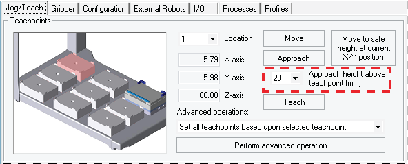
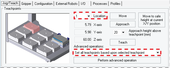
*For optimal performance, teach each of the nine locations independently using the procedure, Setting the first teachpoint.
 
To set the other eight teachpoints:
1
In the Jog/Teach tab, verify that the teachpoint you just taught (Setting the first teachpoint) is set in the Location list.
 
The teachpoint for the other locations will be set based on this one.
2
In the Advanced operations list, select Set all teachpoints based upon selected teachpoint.
3
Click Perform advanced operation.
The VWorks software calculates the teachpoints for the other eight locations, keeping the z-axis coordinate the same and changing the x and y coordinates according to their spacing.
4
Readjust the z-axis height for any positions that are taller than a standard platepad, such as the Orbital Shaking Station.
5
To save the teachpoints, click the Profiles tab and click Update this profile.
Verifying teachpoints for disposable-tip heads
Verify the following:
To verify the tip box labware definition:
1
Open the Labware Editor.
2
In the Pipette/Well Definition tab, verify the following values for the tip box labware definition:
 
To verify the teachpoint accuracy:
 
*For disposable-tip heads, make sure you use a full set of tips to verify each teachpoint.
 
1
Open Bravo Diagnostics, and click the Jog/Teach tab.
2
Click Move to safe height at current X/Y position to move the head up so that you have enough room to remove the single pipette tip from the head barrel.
3
4
a
Click the Processes tab.
b
In the Command to Execute list, select Tips On.
c
Click Execute Command. The head presses down to install the tips, and then moves back up.
5
6
In the Jog/Teach tab, click Move. The head moves to the teachpoint you set in Setting the first teachpoint. You might notice that the A1 tip is not quite in the correct position.
7
Use the Jog Axes controls to move the head A1 tip to the correct position (directly over the crosshairs with paper-thin clearance).
8
When you are finished, click Teach. Verify the information in the message box before you click OK.
9
Repeat step 6 to step 8 for each deck location.
10
To save the changes, click the Profiles tab and click Update this profile.
Verifying teachpoints for pin tools or fixed-tip heads
After setting and saving teachpoints, you should verify each teachpoint.
To verify a teachpoint:
1
In the Jog/Teach tab, set the Location field to the location you want to check.
2
Click Approach.
3
 
a
Click Move to move the A1 needle to the teachpoint.
4
Related information