Bravo Platform User Guide : Setting up the Bravo Platform : Verifying the gripper setup

Verifying the gripper setup
About this topic
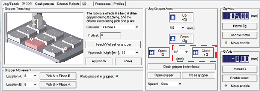
You should read this topic if the Bravo Platform includes a gripper.
This topic describes:
Adjusting the gripper y-axis offset. You should check the gripper y-axis offset when you first set up your Bravo Platform. If necessary, you adjust the y‑axis offset to ensure that the gripper fingers are centered at a platepad. This y‑axis offset is saved with the given profile.
Checking the gripper pick-and-place operations. Use this procedure to ensure the gripper performs the pickup and placement of labware smoothly.
Before you start
Make sure that:
The Bravo gripper fingers are in good condition and aligned with the head. Perform a visual inspection to ensure the gripper fingers are not bent.
Figure. Gripper pads on interior side of gripper finger
 
In Bravo Diagnostics, click the Profiles tab, and initialize the profile that you are checking.
Adjusting the gripper y-axis offset
 
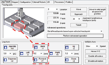
*Before you adjust the gripper y‑axis offset, ensure that the pipettor teachpoints (x-, y-, and z‑axes) have been verified for the given profile and no pipette tips or cartridges are installed on the head.
 
 
*Ensure that you use a standard platepad for the following procedure.


To adjust the gripper y‑axis offset:
1
In Bravo Diagnostics, click the Gripper tab.
2
In the Labware list, select None.
3
 
4
Click Move to move the gripper to the previously saved teachpoint for the selected location.
The Bravo head moves above the deck location, and the gripper assembly extends down (Zg‑axis) so that the gripper fingers are just above the top surface of the platepad.
 
 
5
Visually inspect the spacing between the black rubber gripper pads and the sides of the platepad (y‑axis). Make sure that all the gripper pads have clearance so that the gripper can move down without colliding with the platepad.
Figure. Gripper pad clearance from sides of platepad (top view)
 
6
a
Click the Jog/Teach tab, and ensure that the deck location you selected in step 3 is still selected.
b
Under Jog/Axes, set the Back -Y/Forward +Y increment to a small enough size, such as 0.2 mm.
 
*Make sure you use small enough jog increments to prevent any gripper collisions, which could damage the gripper.
 
 
c
Click Back -Y or Forward +Y as required to adjust the gripper y‑axis position so that the gripper pads will clear the sides of the platepad when you jog down in the next step.
When the following message appears, click OK.
 
7
After ensuring that the gripper pads will not collide with the platepad, set the Down +Z increment to 5.0 mm, and then click Down +Z.
 
*Make sure you do not jog the gripper down more than 5.0 mm at this stage. Jogging down farther will result in a gripper collision with the setscrew on the platepad, which could damage the gripper.
 
When the following message appears, click OK.
 
At this stage, the gripper fingers should be next to the sides of the platepad.
8
a
In the Gripper tab, set the Close +G increment to a small value, such as 0.2 mm, and then click Close +G so that you can clearly see the alignment of the gripper pads with the platepad.
 
 
*Do not click Close gripper. Otherwise, you must redo the procedure.
 
b
In the Jog/Teach tab, set the y‑axis increment to 0.2 mm, and then use the Back -Y and Forward +Y buttons to position the gripper so that the fingers are at equal distances around the platepad.
Ensure the pair of gripper pads on each side are as close as possible to the sides of the platepad without actually touching the platepad.
Note: If a gripper finger is not perfectly straight, one of its gripper pads may be closer than the other to the side of the platepad, as the following figure shows. In this case, adjust the y‑axis using the gripper pad closest to the platepad and the diagonally opposite gripper pad for reference.
Figure. Example of diagonally opposite gripper pads (top view)
 
9
In the Gripper tab, click Teach Y offset for gripper.
10
In the Profiles tab, click Update this profile.
 
 
Checking the gripper pick-and-place operations
To pickup and place labware correctly, the y‑axis offset gripper fingers must be positioned at equal distances from the sides of the labware.
 
 
To test the gripper pick-and-place operations:
1
2
In Bravo Diagnostics, click the Gripper tab.
3
In the Labware list, select the name of the labware type you are using.
4
a
In the Location A list, select the current deck location of the labware.
b
In the Location B list, select the deck location to which the labware will move.
5
Set the Speed to Slow.
6
Click Pick A -> B to pick up the microplate from deck location A and place it on deck location B. Click Pick B -> A to pick up the microplate from deck location B and place it on deck location A.
 
7
8
Set the Speed to Fast, and repeat steps 4, 6, and 7.
9
 
 
Related information