|
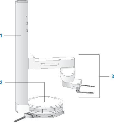
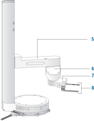
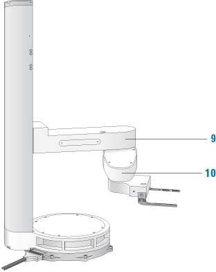
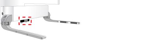
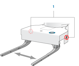
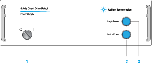
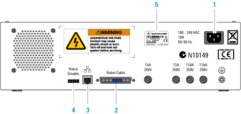
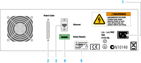
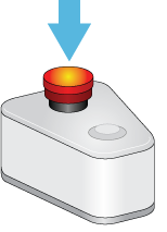
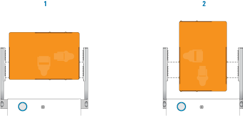
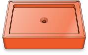
This topic describes the following Direct Drive Robot hardware features:The following diagrams show the main components of the Direct Drive Robot.
The microplate sensor under the robot hand is used to detect the presence of labware in its grip. For more information, see Checking the robot microplate sensor.
Two gripper lead screws on both sides of the robot hand enable you to manually open and close the robot grippers. You need to manually open and close the grippers when setting teachpoints or during troubleshooting. For information about setting teachpoints, see Setting teachpoints. To change the target open and close positions, see Changing the gripper settings.
To turn on the robot, turn the switch to the on (I) position. To turn off the power, turn the switch to the off (O) position. Figure. Power supply G5411-60010
Figure. Power supply G5411-60005
The Direct Drive Robot is equipped with an emergency stop pendant. Pressing the red button on the pendant cuts power to the robot motors and stops the robot during an emergency.If the robot is integrated with other devices in a system, Agilent Technologies recommends that you install a main emergency stop button to cut power to the robot and all devices simultaneously.For detailed safety information, see the Direct Drive Robot Site Preparation and Safety Guide. For instructions on how to recover from an emergency stop, see Recovering from an emergency stop.Figure. Emergency stop pendant.
Supplied with the Direct Drive Robot, the teaching jig allows you to set teachpoints quickly and accurately. The teaching jig can be used for setting teachpoints in the landscape (1) or portrait orientation (2).Note: If size restrictions at teachpoints prevent the use of the teaching jig, you can use the labware intended for the location. For more information, see Setting teachpoints using a labware.
For more information about designating the platepad as a regrip station, see Designating a teachpoint as a regrip station.
Direct Drive Robot description