|
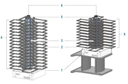
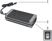
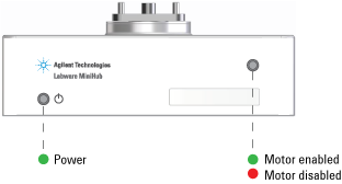
This topic describes the following Labware MiniHub features:The following figure and table describe the main components of the Labware MiniHub.
White structure at the bottom of the Labware MiniHub that attaches the device to the target surface. The base contains the electronics and hosts the connection panel and the status lights.For the BenchCel Configuration, the Labware MiniHub base attaches to an integration-plate assembly (iKit). Typically, the integration-plate is on risers, as the figure shows, for integration with the BenchCel device on risers. However, if the BenchCel device is not on risers, the Labware MiniHub cannot be on risers. Metal spacing blocks that you can add to or remove from the center rod of the Labware MiniHub to adjust the distance between shelves.
• 25.1-mm spacers. Stacked between shelves to accommodate different labware heights.
• 8.4-mm spacers. Stacked above the top-most shelf to fill the space between the top-most 25.1-mm spacer and the cassette cap. These spacers ensure a tight assembly and are only necessary when a subset of the shelves are used. Columns of shelves. The Labware MiniHub consists of four cassettes, each identified by the number on the cassette cap. Metal label with numerical identification of each cassette. The numbers are used in the VWorks software and in Labware MiniHub Diagnostics. Component at the top of the Labware MiniHub that locks the spacers and shelves in place.Figure. Power supply
Labware MiniHub cable connector Connects the Labware MiniHub to the power supply unit. On the base of the Labware MiniHub are two status lights, as the following figure shows.
When you turn on the Labware MiniHub, the red light turns on.When you initialize the Labware MiniHub, the green light turns on.
Labware MiniHub description Labware MiniHub safety