Vertical Pipetting Station User Guide : Autofilling shelf accessories : Setting up a Pump Module

Setting up a Pump Module
About this topic
This topic provides installation instructions for the Pump Module, Tubing Rack, and a reservoir.
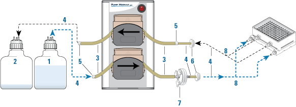
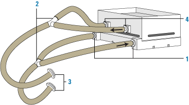
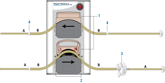
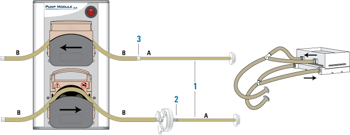
The Pump Module transfers fluids into and transfers waste away from a reservoir. You can use the Pump Module with an Auto Filling Reservoir and a Weigh Shelf or with a Tip Wash Station.
Before you start
 
WARNING Before connecting an accessory, shut down the Vertical Pipetting Station to ensure that the power and air are turned off.
 
IMPORTANT The Pump Module must be internally configured to specify use with or without a Weigh Shelf. If a configuration change is required, contact Automation Solutions Technical Support.
Make sure you are familiar with the setup workflow. See Setup workflow for autofilling shelf.
Installing the Tubing Rack
To install the Tubing Rack on the Vertical Pipetting Station:
1
Secure the Tubing Rack to the Vertical Pipetting Station left side using the three hex-head screws as the figure shows.
2
Figure. Tubing Rack installation


Connecting power and communication
Before you begin
Ensure that the Pump Module location meets the site requirements.
Make sure you have the Pump Module power cord and communications cable.
 
WARNING Ensure that the Pump Module and the associated liquid-handling device, such as the Bravo Platform, are turned off before connecting the cables and routing the tubing.
 
CAUTION Before operating the Pump Module, ensure that the communications cable plug with the EMI filter is connected to the COM IN port. Failure to do so will cause the Pump Module to be non-compliant with the EU Directives for electromagnetic emissions and may cause interference with nearby instruments.
Connecting the cables
To connect the power and communication cables:
1
2
Connect the end of the communications cable with the EMI filter to the Pump Module COM IN port, and connect the other end of the cable to the pump I/O port on the liquid-handling device.
Figure. Pump Module communications cable (1) with EMI filter (2)
 
3
To connect multiple Pump Modules, use a second serial cable to connect the COM OUT port on the first Pump Module to the COM IN port on the second Pump Module.
 
Repeat this step for each Pump Module that is to be controlled by the same device. Up to eight Pump Modules can be controlled in this manner.
4
Connect the provided power cable to the AC power connector on the back of the Pump Module and into an appropriately grounded electrical receptacle.
5
If you are using a Weigh Shelf, Weigh Station, or Weigh Pad, connect its cable to the SHELF A port on the back of the Pump Module.
Routing the tubing
Before you begin
If you are using a Tip Wash Station (also known as a MicroWash Reservoir), make sure you have the inline pump filter.
The following figure shows a tubing configuration example for a single Pump Module and a Tip Wash Station. The table lists the components shown in the figure.
Figure. Example tubing configuration showing components


Workflow for routing the tubing
Perform the following procedures in the order given:
 
Auto Filling Reservoir only. Connect a length of tube B from the overflow gravity-drain to a waste bottle.
To connect tube A to a reservoir:
1
Vertical Pipetting Station only. Place the reservoir on the shelf, and then skip to step 3.
2
a
Fill (input). Cut three lengths of tube A. Two lengths of tubing are for the measured distance from the reservoir ports (1) to a 3-way connector (2). The third length of tubing is for the distance between the 3-way connector and either a quick-disconnect fitting (3) or tubing connector (not shown). Connect the tubing.
b
Empty (output). Cut three lengths of tube A. Two lengths of tubing are for the measured distance from the reservoir output ports (4) to a 3-way connector (2). The third length of tubing is for the distance between the 3-way connector and either a quick disconnect fitting or tubing connector. Connect the tubing.
Note: If the reservoir has one output port, cut one length of tube A for the output tubing.
Figure. Example tubing configuration for a Tip Wash Station: (1) input ports, (2) 3-way connectors, (3) quick-disconnect fittings, and (4) output ports
 
Note: The liquid enters the Tip Wash Station through the two lower input ports and flows up through the chimneys. The overflow of the chimneys flows out through the two upper output ports.
3
Vertical Pipetting Station only. Using the following figure as a guide, route the tubing from the reservoir to the Tubing Rack (1) as follows:
Figure. Example tubing configuration for Vertical Pipetting Station with Tip Wash Station
 
a
Fill (input). Cut three lengths of tube A: two for the measured distance from the reservoir input ports (2) to the 3-way connector (3), and a third for the distance between the 3-way connector and a quick-disconnect fitting (4) on the Tubing Rack. Connect the tubing as the figure shows.
b
Empty (output). If the reservoir has two output ports (5), cut three lengths of tube A following the procedure in step a, and connect the tubing using a 3-way connector (3) as the figure shows. If the reservoir has one output port, cut one length of tube A.
To position tube B in the pump heads:
 
 
1
Determine which of the two pump heads (1) will control the input flow (fill direction) to the reservoir and which will control the output flow (empty direction) to the waste bottle.
Each pump head can be configured in the software to flow in either direction. In the following figure, the lower pump head controls the input flow to the reservoir, and the upper pump head controls the output flow.
Figure. Inserting tubing into the pump heads
 
2
3
a
b
On each side of the pump head, turn the dial (2) to open the clamps (V‑grooves) fully to accommodate the diameter of tube B.
c
Repeat this step for the other pump head.
 
Note: If any creeping of the tubing occurs during operation, tighten the clamps slightly using the clamp dials (2).
Figure. Open pump head (side view) showing fully open clamp and clamp dial
 
4
Tip Wash Station only. For the input flow (fill direction) into the Tip Wash Station, connect the pump filter (3) to tube B between the Pump Module and the Tip Wash Station as the figure shows.
Ensure that the filter is oriented so that the three thumbscrews face toward the Pump Module and the other side of the filter faces toward the Tip Wash Station.
5
Insert a tubing connector (4) on each open end of tube B, as the figure shows.
To connect Pump Module tube B to the tubing from the reservoir:
1
Figure. Tubing from Pump Module to reservoir
 
2
a
Connect one length of tube A to the tube B connector or to the inline filter (2), if applicable, on the input tubing (fill direction) from the Pump Module.
b
3
a
Connect the other length of tube A to the tube B connector (3) on the empty-direction tubing going into the Pump Module.
b
To connect the source and waste bottles to tube B:
1
2
3
4
(Auto Filling Reservoir only) To route the overflow gravity-drain tubing:
1
Vertical Pipetting Station only. Cut a length of tube B for the distance from the reservoir drain port to the Tubing Rack, and from the Tubing Rack to the waste bottle. Attach the tubing using the quick-disconnect fittings.
2
3
 
To complete the Pump Module setup:
1
Vertical Pipetting Station only. Slide the reservoir shelf back and forth to ensure the shelf has enough tubing for unrestricted travel.
2
Turn on the Pump Module, and then turn on the liquid-handling device.
3
IMPORTANT When using Marprene tubing, reset the tension after you run the Pump Module for the first 30 minutes. To reset the tension on the tubing, open the flip-top cover of the pump head, allow the tube to settle naturally across the rollers, and then reclamp the tube.
IMPORTANT When the Pump Module is not in use, lift the flip-top cover on each pump head to prevent flattening the tubing and to help maximize the tubing life.
Removing a Pump Module
To remove the Pump Module:
1
Using the automation control software, run the Pump Module and drain the reservoir until empty.
2
Turn off the Pump Module, and then turn off the liquid-handling device.
3
Disconnect the Pump Module power and communication cables. Unplug the Weigh Station cable from the Pump Module.
4
5
6
Remove the tubing from the Pump Module and from the source and waste bottles.
 
 
Related information
 
Starting up and shutting down the Vertical Pipetting Station
Installing a Weigh Shelf