Connection panel description
Bravo rear connection panel
The following figure and table describe the connection panel at the rear of the Bravo Platform.
Figure Connection panel on back of Bravo Platform
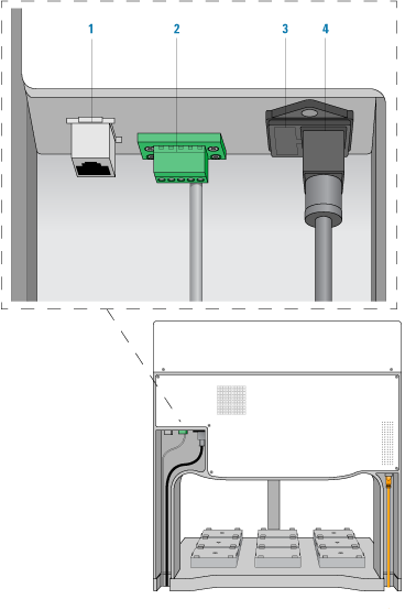 |
Item | Feature | Description |
|---|---|---|
1 | Ethernet port | Connects the Ethernet card in the controlling computer to the Bravo Platform. |
2 | Pendant port | Connects the emergency-stop pendant and a Bravo light curtain to the Bravo safety interlock circuit. The connection is made through an emergency-stop control, such as the Robot Disable Hub. |
3 | Fuse holder | Houses the AC inlet fuse and a spare fuse for the Bravo Platform. |
4 | AC power entry | Connects the Bravo power cord to an AC outlet with a grounded circuit. |
Pump I/O port
The following figure shows the Pump I/O port on the back of the Bravo Platform. The table below describes the Pump I/O port in detail.
Figure Pump I/O port (Bravo Platform back view)
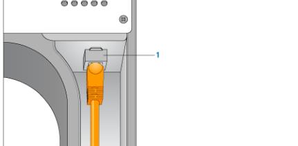 |
Item | Feature | Description |
|---|---|---|
1 | Pump I/O port | An RJ-45 I/O port that connects the Pump Module to the Bravo Platform. The connection is made with a straight-through shielded Cat-5 or Cat-6 (Ethernet) cable. |
Related information
For more information about... | See... |
|---|---|
Installing and connecting the Bravo Platform | G5562A, G5563A Bravo Platform Safety and Installation Guide |