|
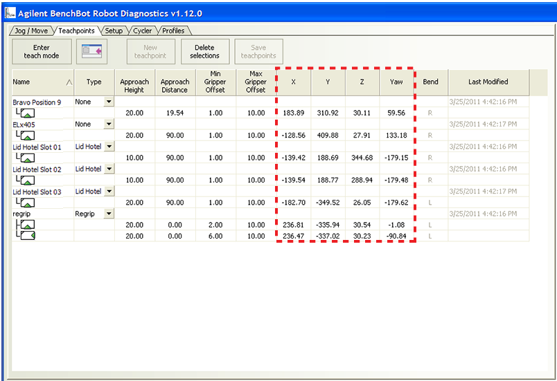
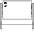
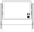
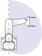
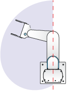
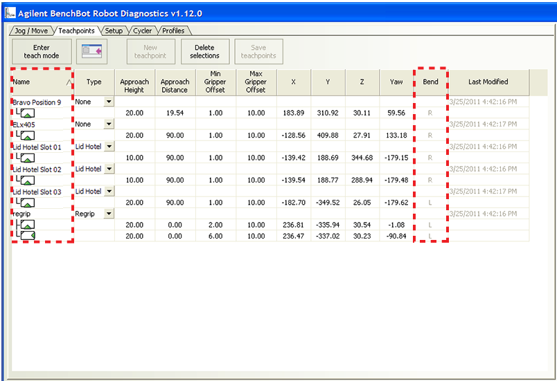
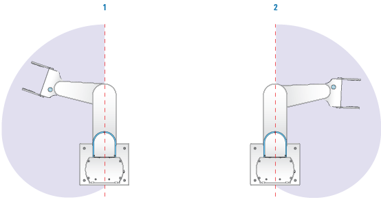
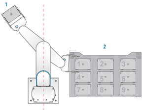
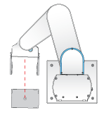
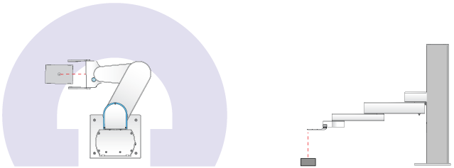
Planning BenchBot Robot teachpoints
•
IMPORTANT The maximum teachpoint height (427.5 mm) is the sum of the teachpoint's z-axis coordinate plus the approach height. For a description of the approach height, see Teachpoint components and Setting the Approach Height and Approach Distance parameters.IMPORTANT To optimize performance results, teachpoints should be set within 30 mm to 415 mm along the z-axis.Figure. BenchBot Robot teachpoint zone top view (left) and side view (right)
A BenchBot Robot teachpoint consists of the following:
• A set of coordinates define each teachpoint: (x, y, z, yaw). The coordinate information consists of the x-, y-, and z-axis values. The angle of the labware or grippers, yaw (n°), is also included with the coordinate information. All coordinate values are measured with respect to the center of the labware.
Away from the robot grippers in either labware orientation
IMPORTANT The software will not permit you set teachpoints within the robot zone. Prompts will display to let you know that you are in the robot zone. For information about the robot zone, see Retracting the robot into the robot zone.
• Labware orientation. Determine the best labware orientation (landscape or portrait) for the location. The orientation might be determined by device requirements. For example, the Labware Stacker requires labware to be in the landscape orientation, but the MiniHub permits labware to be in either the landscape or portrait orientation.
• A1-well orientation. Determine the A1-well orientation of the labware. In general, for devices that require the landscape orientation, such as the Labware Stacker and the Centrifuge, the optimal A1-well orientation is typically away from the grippers. For storage devices that require the portrait orientation, the optimal A1-well orientation depends on the requirements at other teachpoints in the system. See Examples.
• Arm orientation. For the best robot freedom of movement and approach distances, use the right-arm orientation for teachpoints on the robot’s left side (1) and use the left-arm orientation for teachpoints on the robot’s right side (2). This recommendation becomes a requirement when setting teachpoints next to and behind the robot shoulder.IMPORTANT For teachpoints that are next to or slightly behind the robot shoulder, make sure two sides of the teachpoint stage are parallel to the side of the robot base. See Examples.
• Add multiple orientations to a teachpoint. A regrip station is used if the robot needs to change the orientation of the labware it is holding as it transfers labware from one location to another. To reduce the number of regrips necessary, you can add multiple orientations to a teachpoint. For more information, see Adding multiple orientations to a teachpoint.
• Maximize the gripper offset ranges. A regrip station is used if the robot needs to adjust gripping height as it transfers a labware from one location that requires a gripper height that is different from the next location. To provide the system with the greatest flexibility for identifying a grip position that works for all locations, you should set the widest possible range for each gripper offset parameter. For more information about gripper offset ranges, see Setting the Min and Max Gripper Offset parameters.
• Set Approach Distance at the smallest possible value. In general, rotating robot movements are faster than linear movements. To ensure that the robot rotates from the robot zone directly to the teachpoint approach height, set the Approach Distance at 0. If obstacles near or at the teachpoint do not permit the rotating movement, set the Approach Distance at the smallest possible value for the location. For more information, see Setting the Approach Height and Approach Distance parameters.In the following example, the platepad (1) is on the left side of the robot. When setting the teachpoint at the platepad, use the right-arm orientation.The Bravo Platform (2) is on the right side of the robot. When setting teachpoints at the Bravo Platform, use the left-arm orientation.