Direct Drive Robot User Guide : Setting teachpoints : Setting teachpoints

Setting teachpoints
About this topic
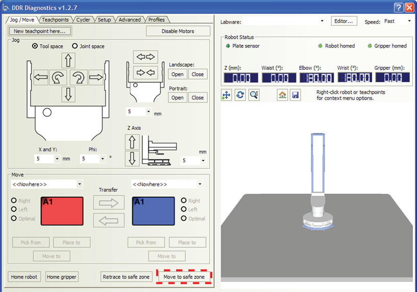
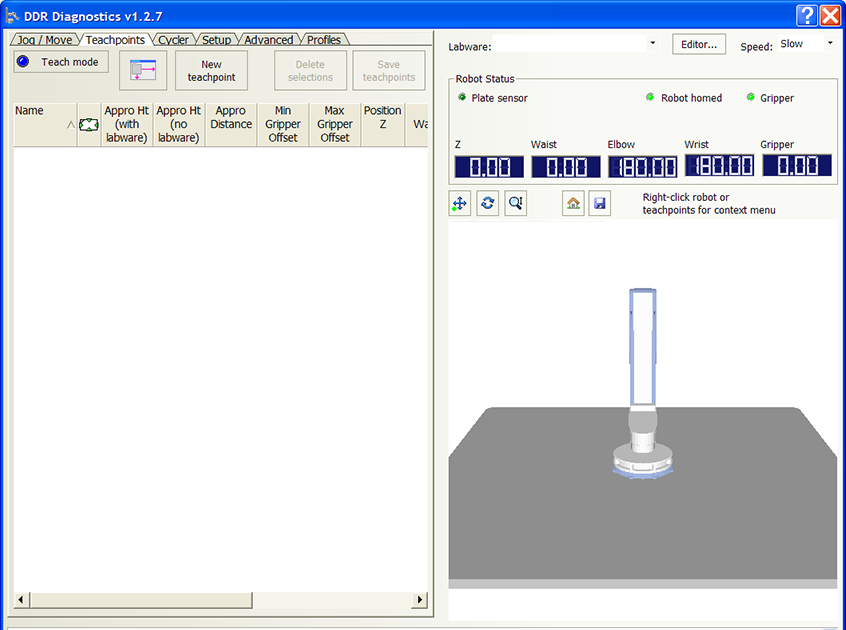
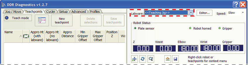
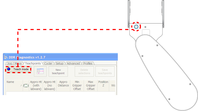
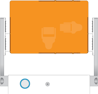
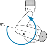
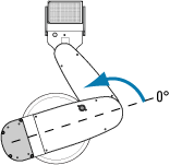
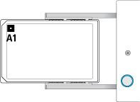
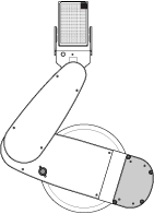
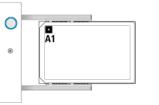
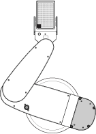
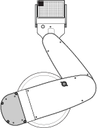
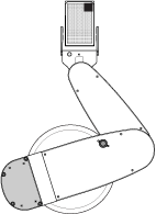
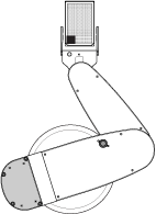
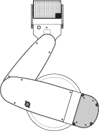
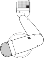
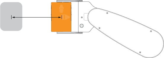
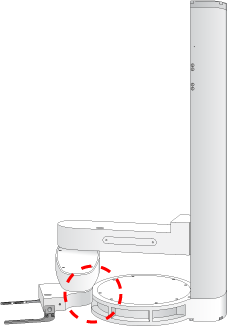
Depending on the type of device, the teachpoint setting procedure can vary. This topic provides basic teachpoint setting concepts: how to use the supplied teaching jig or the desired labware to set, verify, and edit Direct Drive Robot teachpoints.
Teachpoint files
The teachpoints you set are saved in the XML format in a teachpoint file. The default teachpoint file name is Teachpoints_<profilename>.xml, where <profilename> is the name of the profile. The software saves the file in the C:\Program Files\Agilent Technologies\Settings\DDR folder. However, you can select another file name and location when saving the file.
 
You can have multiple teachpoint files for each Direct Drive Robot if a device needs to serve multiple purposes. For example, a platepad can be taught as a platepad or as a regripping station. You can also have multiple teachpoint files for the system if a device is only used in some protocols but not others. For example, if a device is installed on a docking table and can be removed when it is not in use.
 
The teachpoint file is referenced by a profile. For information about profiles, see Creating Direct Drive Robot profiles.
Workflow
The workflow for setting a Direct Drive Robot teachpoint is as follows:
 
Optional. Designate a teachpoint as a regrip station.
Optional. Selecting the All regrip stations are safe from above option.
10 
11 
Before you start
Make sure:
You have the provided Direct Drive Robot teaching jig. If size restrictions at teachpoints prevent the use of the teaching jig, use the labware intended for the location. See Setting teachpoints using a labware.
Installing and removing the teaching jig in the robot grippers
 
 
IMPORTANT If size restrictions at a teachpoint prevent the use of the teaching jig, use the labware intended for the location. For information, see Setting teachpoints using a labware.
To install the teaching jig:
1
In DDR Diagnostics, click the Jog/Move tab, and then click Move to safe zone. The robot moves into its safe zone.
 
2
In DDR Diagnostics, click the Teachpoints tab.
 
3
In the Labware list, select Teaching jig.
 
4
Click Teach Mode. The blue light on the robot hand turns on to indicate that it is in the teach mode. You should be able to move the robot arm without resistance.
IMPORTANT Always move the robot arm slowly when in the Teach Mode.
 
5
6
 
7
 
8
To remove the teaching jig:
1
2
3
 
Creating a new teachpoint
 
 
To create a teachpoint:
1
a
b
2
3
Note: The blue light does not flash if the robot is at a location that is outside of its travel limits. Move the teachpoint location and try again.
 
If it is not possible to access the blue button on the robot hand, you can click the New teachpoint button in the Teachpoints tab.
 
4
To view the entire teachpoints table, click the 
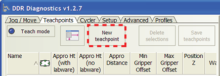
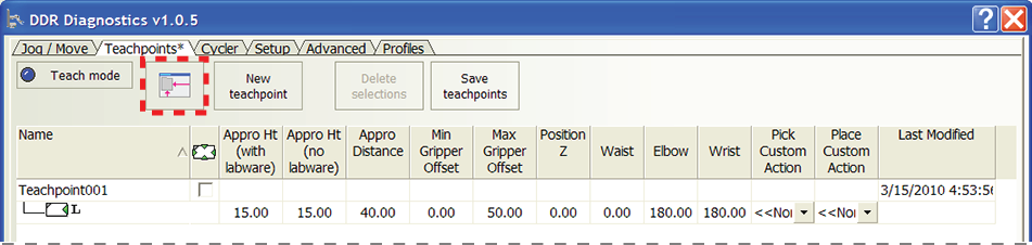
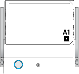
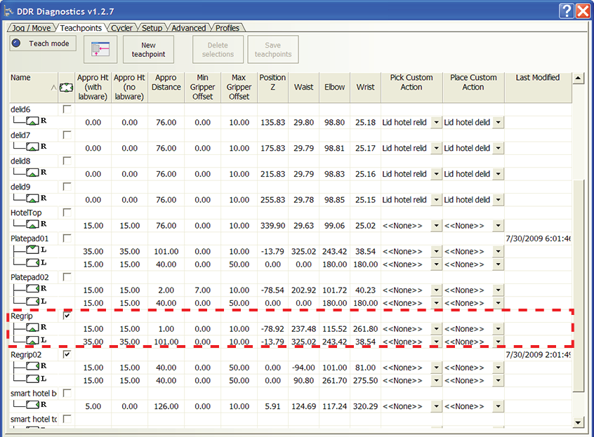
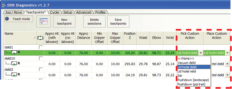
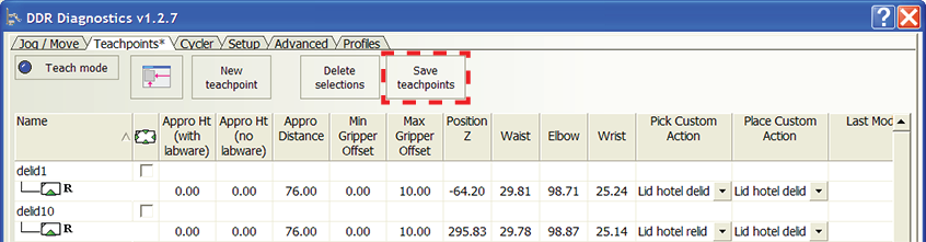
(Maximize/Minimize) button. The table expands so that all of the columns are displayed in the tab.
 
Naming the teachpoint
To name the teachpoint:
Double-click the Name box and type a new name for the teachpoint. Use a name that describes the location, such as the device name (for example, PlateLoc - 1).
Specifying the A1-well orientation
The icon under the teachpoint name indicates the following:
 
 
Left (L) or right (R)
Common orientations
Eight orientations are possible for each teachpoint, based on different A1-well, labware, and robot-arm orientations. The following table presents six common orientations.
 
Atypical orientations
The following table presents two atypical orientations. These orientations are used only when:
 
Designating a teachpoint as a regrip station
A regrip station is a location that enables the robot to:
Note: Regrip stations cannot be used for other purposes such as deadlock avoidance.
To accommodate different labware orientations, add multiple orientations to the regrip teachpoint. In the following example, the Regrip teachpoint accommodates both the right- and left-arm orientations, with the landscape labware orientation and the A1 well away from the grippers.
 
To designate a teachpoint as a regrip station:
Select the Regrip Station check box.
 
To add additional orientations to the regrip teachpoint:
1
2
By default, a new teachpoint will always have the A1-away orientation. When adding multiple teachpoints at a regrip station, if two of the teachpoints have the same labware and robot-arm orientation, and it is difficult to tell which one should have the A1-well away or toward assignment unless you see the actual robot position:
a
 
b
In the following example, two teachpoints have the same labware and robot-arm orientations: landscape and right-arm. However, depending on the robot approach, the A1-well orientation will be different.
 
c
Click OK to exit the dialog box and, if necessary, set or correct the A1-well orientation setting.
3
 
4
Setting the approach height
Approach height is the height clearance, in millimeters, the robot must maintain above the teachpoint as it moves towards or away from the teachpoint.
 
You can reduce the approach height to prevent collision with shelves or other obstacles above the teachpoint. However, make sure there is sufficient clearance below the labware to prevent collision with raised tabs or other obstacles at the teachpoint.
 
IMPORTANT The approach height value works in conjunction with the approach distance to clear obstacles near or at the teachpoint. Therefore, before setting the approach height value, you should determine the approach distance value to use. See Setting the approach distance.
If Approach Distance is set at the default value:
Note: If the teachpoint does not have any obstacles on the front or sides, you can set Approach Ht (no labware) at 0. The robot will approach the teachpoint at the higher of the teachpoint or labware minimum gripper offset value.
If Approach Distance is less than the default value:
In general, if a teachpoint has raised tabs only at the front of the teachpoint, the Approach Ht (with labware) value should be greater than the Approach Ht (no labware) value.
Agilent Technologies recommends the following Approach Ht (with labware) values:
 
Vertical Pipettor shelf with tipbox
Plate Hub Carousel Carousel or Plate Hotel with
standard labware
* Required approach height for the device
To set the Approach Ht (with labware) and Approach Ht (no labware) parameters:
Double-click in the Approach Ht box and type the desired value. The default value for both parameters is 15 mm.
Setting the approach distance
Approach distance is the distance, in millimeters, from the teachpoint. Within this distance, the robot must:
 
You use the approach distance to provide clearance:
For example, you can use the approach distance parameter so that the robot grippers can enter and exit a device such as the Microplate Centrifuge without bumping into the sides of the narrow entryway.
When determining the value to specify, manually move the robot away from the teachpoint until the grippers and the teaching jig are clear of the edge of the teachpoint and obstacles near the teachpoint.
In addition, consider the following:
Before setting Approach Distance at 0, you should consider the obstacles surrounding and at the teachpoint. If obstacles near or at the teachpoint do not permit the rotating movement, set Approach Distance at the smallest possible value for the location.
 
 
To set the Approach Distance parameter:
Double-click in the Approach Distance box and type the desired value. The default value is 75 mm for the landscape orientation and 125 mm for the portrait orientation.
Setting the gripper offset parameters
About gripper offset parameters


The robot gripper offset range parameters tell the Direct Drive Robot where to grip a given labware type when transferring it from one device to another. Each device within a system can pose different accessibility challenges when transferring the labware. For example, some devices can have a deep, recessed area, whereas others are more flat. Some devices might have tall flanges that make it impossible for the robot to grip a microplate at a very low point.
The Direct Drive Robot uses three types of gripper offset ranges to determine the most compatible grip position for the labware type:
1
Gripper offset range for the labware. Specified on the Direct Drive Robot tab in the Labware Editor for each labware definition.
2
Gripper offset range for pick-location device. Specified in the DDR Diagnostics software for a given device (device A).
3
Gripper offset range for place-location device. Specified in the DDR Diagnostics software for a given device (device B).
If the three gripper offset ranges overlap, the robot will use the smallest common gripper offset to perform a direct labware transfer from device A to device B without regripping the labware. If the three ranges do not overlap, the software attempts to plan a path through one or more regrip stations. If the robot cannot perform the transfer, an error message appears at the time of the requested labware transfer.
To provide the system with the greatest flexibility for identifying a grip position that works for all locations, you should set the widest possible range for each gripper offset parameter.


Note: To catch and correct potential labware transfer errors, Agilent Technologies recommends that you verify the teachpoints and perform a dry run.
Before you set the gripper offset parameters
Under some circumstances, you should consider the gripper offset ranges of more than two teachpoints to avoid a regrip. For example, a labware will be delidded as it moves from the pick location (device A) to the place location (device B). In this case, the gripper offset range for the delid teachpoint must also overlap with the gripper offset range for the labware, device A, and device B.
Procedure
To set the Min gripper offset and the Max gripper offset parameters for a device:
Double-click the Min gripper offset and Max gripper offset box and type the desired values:
Minimum gripper offset. The vertical distance (mm) from the teachpoint to the lowest point where the robot grippers can hold the microplate securely. The default value is 0 mm.
Maximum gripper offset. The vertical distance (mm) from the teachpoint to the highest point where the robot grippers can hold the microplate securely. The default value is 10 mm.
 
IMPORTANT For regrip stations, make sure the gripper offset range can accommodate all types of labware.
Setting the Position Z, Waist, Elbow, and Wrist parameters
 
If necessary, you can fine-tune the teachpoint coordinates using the following parameters:
Position Z. The z-axis coordinate of the robot, measured in millimeters.
Waist. The waist joint coordinate.
Elbow. The elbow joint coordinate.
Wrist. The wrist joint coordinate.
To set a coordinate parameter:
Double-click in the Position Z, Waist, Elbow, and Wrist box and type the desired value.
Note: You can also use the jog method when fine-tuning. For instructions, see Editing existing teachpoints.
Selecting custom actions
Custom actions are special pick-and-place actions that the robot will perform after it arrives at the teachpoint. The set of custom actions include:
Delidding at a Lid Hotel Station or a Vacuum Delid Station
Relidding at a Lid Hotel Station
You can select a custom action for any teachpoint.
To select a custom action for a teachpoint:
1
Use the Pick Custom Action to:
Relid labware at the Lid Hotel Station. From the Pick Custom Action list, select Lid Hotel relid.
Note: You can select a custom action for each storage bay in the Lid Hotel Station. Do not assign a custom action for the platepad at the top of the station.
Stir the labware at the teachpoint. From the Pick Custom Action list, select Stir.
2
Use the Place Custom Action to:
Delid labware at the Lid Hotel Station or the Vacuum Delid Station. From the Place Custom Action list, select either Lid Hotel delid or Vacuum delid.
Note: You can select a custom action for each storage bay in the Lid Hotel Station. Do not assign a custom action for the platepad at the top of the station.
From the Place Custom Action list, select either Pushdown (landscape) or Pushdown (portrait).
 
Saving the teachpoints
The teachpoint information is stored in:
When you create or modify teachpoints without saving them, the changes are kept in computer memory only. Saving the teachpoints in DDR Diagnostics updates the teachpoints file and the information in the firmware.
Note: Saving teachpoints adds new teachpoints or updates only those teachpoints that have been modified in DDR Diagnostics. Saving teachpoints does not overwrite all of the existing teachpoints. For example, a teachpoint file contains teachpoints A and B. You modify teachpoint B and add teachpoint C. When you save the teachpoints, teachpoint C is added, and teachpoint B is updated. Teachpoint A is not touched.
To save the teachpoints:
1
Click Save teachpoints.
 
If there are any errors or warnings, such as an out-of-bounds parameter value, the software will list them in the Teachpoint Errors and Warnings dialog box.
 
2
Click OK to close the dialog box and return to the teachpoints table. Notice that error and warning symbols appear in the teachpoints table.
3
 
4
Be sure to remove the teaching jig from the robot grippers when you are finished. See Installing and removing the teaching jig in the robot grippers.
Selecting the All regrip stations are safe from above option
The All regrip stations are safe from above option enables the robot to rotate its wrist above the regrip station while it prepares to change labware orientation.
If the option is selected, the robot will place the labware at the regrip station, lift its arm to the specified Approach Ht (no labware) distance above the regrip station, rotate its wrist, and then pick up the labware using the new orientation. The robot does not retreat into the safe zone during this process.
If the option is not selected, the robot will place the labware at the regrip station, retreat into the safe zone, and then pick up the labware at the regrip station using the new labware orientation. The specified Approach Ht and Approach Distance values are used during the retreat and pickup movements.
After you have finished setting all the teachpoints, review the list in the teachpoints table. You can select the All regrip stations are safe from above option in the Profiles tab if:
There is sufficient clearance above all regrip stations to permit the robot to rotate its wrist during a labware orientation regrip process.
To see where you select this option in the Profiles tab, see Creating Direct Drive Robot profiles.
Related information
 
Robot Diagnostics
Quick reference of DDR Diagnostics commands and parameters