Installing and setting up a Vacuum Filtration Station
About this topic
This topic describes how to set up the Vacuum Filtration Station on the Bravo Platform.
Before you start
The Vacuum Filtration Station may be installed on a standard Bravo Platform and is compatible with the Series III disposable-tip heads only. Agilent Technologies recommends installing the station on a short platepad (SRT platepad). The Vacuum Filtration Station is not supported on the SRT Bravo Platform.
The following table presents the workflow for setting up and automating the assembly and disassembly processes for the Vacuum Filtration Station.
Step | For this task... | See... |
|---|---|---|
1 | Determine which components of the Vacuum Filtration Station are required for your labware. | |
2 | Install the Vacuum Filtration Station. | |
3 | In Diagnostics, configure the Vacuum Filtration Station in the device profile. | |
4 | In the VWorks Labware Editor, ensure that the labware definitions are correct for the filter and collection plates that will be placed on the Vacuum Filtration Station during a protocol run. Set the microplate parameters and the Bravo gripper offset for the labware. | VWorks Automation Control Setup Guide |
5 | In the VWorks software, add one or more pairs of the vacuum assembly and disassembly tasks in the protocol. | VWorks Automation Control User Guide |
Component descriptions and options
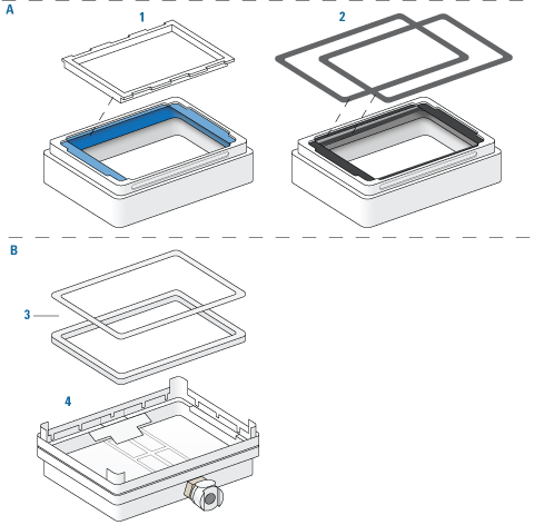
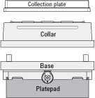
The Vacuum Filtration Station applies vacuum to filter the contents of microplates placed on the station. The station consists of a collar and a manifold base that can be assembled and disassembled automatically. The following figure shows the primary components.
Figure Vacuum Filtration Station components: A collar options, B base and optional inserts
 |
Item | Name. | Description |
|---|---|---|
1 | Collar with blue gasket and clear gasket frame support | The top of the vacuum manifold, which can be placed in different stacking configurations, as described in the following section. The collar is available in standard and deep-well models. The deep-well collar is required to accommodate plate-on-plate stacking for deep-well microplates. The Bravo device profile configuration specifies the collar size. Note: Different types of gasket frame inserts are available. See the manufacturer’s user documentation for a detailed description. |
2 | Black gaskets for collar | The same collar as item 1, except the flexible blue gasket is replaced with two black gaskets that are held in place by an adhesive. One black gasket adheres to the top of the collar, and the second black gasket adheres to the underside surface of the collar top to maintain the correct spacing underneath the collar. Use the black gaskets instead of the blue gasket in the following configurations: • If the type of filter plate cannot be seated on the blue gasket fitted with the clear gasket frame, you may replace the blue gasket with the two black gaskets to accommodate the filter plate. In this case, adhere one black gasket on top and one black gasket on the underside of the collar. • If the filter plate nozzles are too short to reach the wells in the collection plate underneath the collar, you may omit the black gasket on the underside of the collar. If you do this, ensure that you specify the collar option in the Bravo device profile as Black gasket on top side only. |
3 | Inserts | The white plastic spacers that can be placed in the base manually before starting the protocol, if required, to raise the height of a collection plate that sits underneath the collar. Two sizes are available. You may use multiple inserts in combination for a combined height of 15 mm, maximum. |
4 | Base | The bottom of the vacuum manifold that connects to the vacuum source. The base should be installed on a short platepad to compensate for the height of the assembled station including labware. |
For more details about the Vacuum Filtration Station collar and base, see the Millipore user documentation.
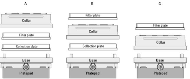
Supported stacking configurations
In addition to the basic configuration of the collar stacked on the station base, other configurations can be automatically assembled and disassembled during a protocol run. The common configuration options are as follows:
• Configuration A. The filter and collection plates are part of the station assembly.
Note: Double-filtration is possible in configuration A by including one filter plate as part of the station assembly and a second filter plate on top of the vacuum collar.
• Configuration B. The filter plate is not part of the station assembly. The robot will move the filter plate to the station during the protocol run after the assembly process is finished.
• Configuration C. The filter plate is not part of the station assembly. The robot will move the filter plate to the station during the protocol run after the assembly process is finished.
 |
Installing the station
Before you start
Make sure you have the following:
• Vacuum Filtration Station kit. Contains the vacuum manifold base and collar, tubing for robotic and manual setups, waste bottle, and filter.
• M1.5 hex wrench
• Vacuum source. Use one of the following:
– House vacuum and pinch-valve module
– Agilent ME4C NT VARIO Pump
For detailed information, see the ME4C NT VARIO Pump manual at https://www.vacuubrand.com.
• Available serial port on the controlling computer
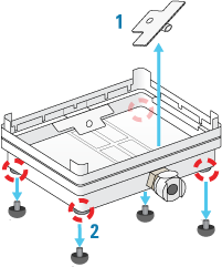
Figure Removal of (1) plastic plug from vacuum port and (2) rubber feet from base
 |
Determining the installation location
Make sure that the installation location for the Vacuum Filtration Station base enables routing of the tubing.
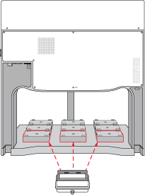
For example, on the Bravo deck, you can install the Vacuum Filtration Station on a platepad at deck location 1, 2, or 3 if you want to route the tubing out the rear opening.
Figure Installation options on the Bravo deck: location 1, 2, or 3 on the back row
 |
Installing the station
To install a Vacuum Filtration Station:
1 Place the base of the Vacuum Filtration Station on the platepad (typically, an SRT platepad).
Ensure that the base sits level and that the vacuum port faces in the correct orientation for the tubing exit.
2 To secure the base, use a M1.5 hex wrench to tighten the setscrew in the platepad tab.
3 Connect the Vacuum Filtration Station as required for the type of vacuum source:
• House vacuum with pinch-valve module.
• Agilent VARIO Pump.
Connecting to house vacuum with the pinch-valve module
Perform the following tasks to connect the pinch-valve module to the house vacuum source.
Step | For this task... | See... |
|---|---|---|
1 | Connect the manual vacuum pressure control-valve-and-gauge assembly. | |
2 | Connect the pinch-valve tubing and cables. | |
3 | Set the pressure using the manual vacuum control-valve and gauge. |
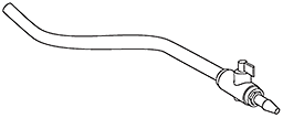
Connecting the control-valve-and-gauge assembly
Refer to the following figure to connect the manual pressure control-valve-and-gauge assembly.
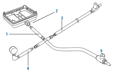 |
To connect the pressure control-valve-and-gauge assembly:
1 Ensure that the base (manifold) of the Vacuum Filtration Station is installed on the Bravo platepad.
2 Connect the coupling insert on the end of the four-way connector (1) to the quick-disconnect fitting (2) on the base. Push the coupling insert until it clicks.
3 Connect the coupling insert on the end of the manual vacuum control valve tubing (3) to the quick-disconnect fitting on the short arm of the four-way connector.
4 Connect the coupling insert on the end of the vacuum pressure gauge tubing (4) to the quick-disconnect fitting on the long arm of the four-way connector.
5 Optional. Disconnect the manual on/off toggle switch (5) from the end of the tubing. This toggle switch is not required for the setup.
Connecting the pinch valve tubing
Note: The pinch-valve tubing can collapse with regular use over time, resulting in inadequate vacuum flow for the Vacuum Filtration Station. Replace the tubing periodically to keep the Vacuum Filtration Station functioning as intended.
The following figure shows the connections from the Vacuum Filtration Station to a vacuum source via a pinch-valve module.
Figure Vacuum Filtration Station connections for a pinch-valve module
 |
Item | Name | Description |
|---|---|---|
1 | Vacuum control valve-and-gauge assembly | Helps regulate the vacuum pressure to prevent the pinch-valve module tubing from collapsing. |
2 | Pinch-valve module assembly | |
• 3-way connector | Branches the tubing from the Vacuum Filtration Station base to the vent and valve ports on the pinch-valve module. | |
• Pinch-valve module | Houses the electronics that communicate with the software to automatically open, close, or vent the vacuum pressure. | |
• Vent port | Routes the vent tubing on the pinch-valve module. | |
• Valve port | Routes the tubing from the vacuum source to the Vacuum Filtration Station through the waste bottle. | |
3 | Waste bottle and tubing | Collects the waste solution from the filtration process. |
4 | Filter | Prevents particulates from the entering the vacuum supply. |
5 | House vacuum | Provides the vacuum supply for the filtration process. |
6 | Power cord | Connects the pinch-valve module to an AC outlet. |
7 | Communication cable, serial | Connects the pinch-valve module to the com port on the controlling computer. |
To connect the Vacuum Filtration Station using the pinch-valve module:
1 Ensure that the vacuum source is turned off.
2 Connect the tubing from the vacuum control valve-and-gauge assembly (1) to the open three-way connector tubing on the pinch-valve module assembly (2).
 |
Note: The remaining tubing from the three-way connector is pre-assembled: One tube connects to the vent port, and the second tube connects through the valve port.
3 Connect the open end of the pinch-valve tubing from the valve port (2) to a port on the waste bottle (3).
4 Connect tubing between the second port of the waste bottle (3) and an in-line filter (4).
5 Connect the tubing between the in-line filter and the vacuum source (5).
6 Connect the power cable (6) from the pinch-valve module to an AC outlet.
7 Connect the communications cable (7) from the pinch-valve module to a com port on the controlling computer.
Setting the vacuum pressure
To set the regulated vacuum pressure for the pinch valve:
1 Place a solid-bottom collection plate or the teach plate on top of the installed collar on the Vacuum Filtration Station.
 |
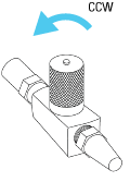
2 At the vacuum control valve, turn the knob fully counterclockwise (CCW) so that the valve is completely open, preventing any vacuum pressure in the tubing.
 |
3 Turn on the vacuum source.
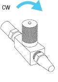
4 While observing the manual pressure gauge, slowly turn the control-valve knob clockwise (CW), gradually closing the line and increasing the vacuum until you achieve the desired vacuum pressure (8.46 inHg, maximum).
 |
If the vacuum pressure exceeds 8.46 inHg, the pinch valve tubing may collapse. If this occurs, turn off the vacuum source to the pinch valve and turn the control-valve knob counterclockwise to eliminate the vacuum pressure. You may need to massage the tubing slightly to open it up again.
Now you are ready to configure the Vacuum Filtration Station in the software. See Configuring the Vacuum Filtration Station in Bravo Diagnostics.
Connecting and configuring the Agilent VARIO Vacuum Pump
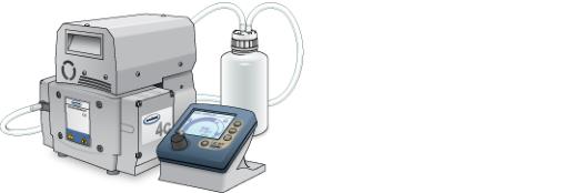
The following figure shows the Agilent ME4C NT VARIO Vacuum Pump.
Figure Agilent ME4C NT VARIO Vacuum Pump
 |
For detailed instructions about the VARIO pump, see the manufacturer’s Instructions for use, provided with the pump.
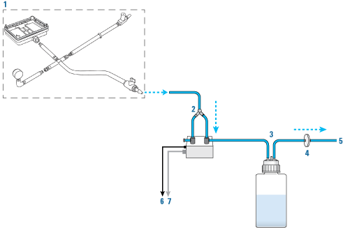
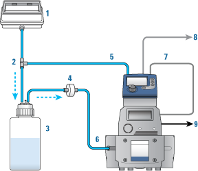
The following figure shows the connections for a Vacuum Filtration Station that uses the ME4C NT VARIO Vacuum Pump.
Figure Vacuum Filtration Station connections for ME4C NT VARIO Vacuum Pump
 |
Item | Name | Description |
|---|---|---|
1 | Vacuum Filtration Station | Contains a vacuum port on that base that connects to the tubing. |
2 | Three-way connector | Branches the tubing from the station’s base to the pump and the waste bottle. |
3 | Waste bottle | Collects the waste solution from the filtration process. |
4 | Filter | Prevents particulates from the entering the vacuum supply. |
5 | Controller | Controls the pump unit. |
6 | Pump unit | Provides the vacuum supply to the station. |
7 | Power supply cable | Routes power between the pump and the controller. |
8 | Communication cable, serial | Connects pump controller to a com port on the controlling computer. |
9 | Power cord | Connects the pump to an AC outlet. |
To connect the Vacuum Filtration Station to the ME4C NT VARIO Vacuum Pump:
1 Make sure the Vacuum Filtration Station base is installed on the platepad.
2 Using the three-way tubing connector:
a Connect the tubing with the quick-disconnect fitting to the port on the station base (1), and connect the other end to the three-way connector (2).
b Connect the input tubing from the waste bottle (3) to the three-way connector.
c Connect tubing from the three-way connector to the port on the back of the controller (5).
3 Connect the output tubing from the waste bottle (3) to the filter (4), and connect the output tubing from the filter to the inlet on the front of the pump (6).
4 Carefully, connect the pump’s power supply cable (7) to the 4-pin connector on the back of the controller (5).
5 Connect the communications cable (8) from the pump controller to a com port on the controlling computer.
6 Connect the power cord (9) from the pump to an AC outlet.
7 Configure the controller communication settings as described in the following procedure.
8 Turn on the controlling computer.
9 At the back of the pump, press the power switch to the on (|) position.
10 Configure the com port for the Vacuum Filtration Station and other settings in Bravo Diagnostics. For instructions, see Configuring the Vacuum Filtration Station in Bravo Diagnostics.
To configure the controller communication settings for the pump:
1 At the controller panel, locate the power button (1) and the selection knob (2), as the following figure shows.
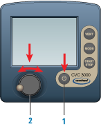 |
2 If the controller power is off, press the power button to turn on the display.
Note: The controller display will turn on automatically if the controller power button was already set to on.
3 Access the controller configuration display as follows:
a Press the selection knob to display the settings menu. Turn the knob to move the selector to Configuration, and then press the knob to make the selection.
b In the Configuration display, turn the knob to move the selector to RS‑232, and then press the knob to make the selection.
c In the RS-232 configuration display, ensure that the parameters are set as follows:
RS-232 parameters | Values |
|---|---|
Baud | 9600 |
Parity | 8-N-1 |
Handshake | None |
Remote | Off Note: Later, after you initialize the Vacuum Filtration Station in your automation software, the Remote setting will change to On automatically. |
To change a value, turn the selection knob to the desired parameter, press the knob to access the value, and then turn the knob to change the value. Press the knob again to confirm the new setting.
d Use the selection knob to move the selection to Back, and press the knob to exit each display until you exit the Configuration display.
4 Ensure that the controller displays Vac control.
The PC icon  will appear after you initialize the Vacuum Filtration Station in your automation software, indicating that the pump is under remote control.
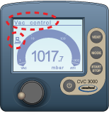 |
Note: While the PC icon appears on the controller display, the Vacuum Filtration Station is under the control of the computer, and you can no longer control the pump locally using the controller display.
If you want to reset the controller, press the power button to turn it off, set the power switch on the back of the pump to off. Wait a minute, and then turn on the pump and turn on the controller again.
For additional information on the VARIO pump, see the manufacturer’s user documentation.
Uninstalling the Vacuum Filtration Station
To uninstall the station:
1 Turn off the vacuum.
2 Disconnect the pump controller or pinch-valve communications cable from the com port on the computer.
3 If applicable, disconnect the pinch-valve module from the vacuum source.
4 Disconnect the tube from the Vacuum Filtration Station.
5 Remove the set screw that is holding the station base to the platepad.
6 Remove the Vacuum Filtration Station from the platepad.
Configuring the Vacuum Filtration Station in Bravo Diagnostics
To configure the Vacuum Filtration Station:
1 In Bravo Diagnostics, click the Profiles tab, and verify that the correct profile is initialized.
2 Click the Configuration tab.
3 In the Locations list, select the deck location of the Vacuum Filtration Station base.
4 In the Location is configured as list, select Accessory. The Accessories Wizard opens.
5 In the Location list, confirm the deck location of the Vacuum Filtration Station base, and then click Next.
6 In the Accessory list, select Vacuum Filtration Station, and then click Next.
7 In the “Vacuum Filtration Station” properties table, set the following:
a Serial Port. The com port on the controlling computer to which the communications cable from the pinch-valve module or the pump connects.
b Select one of the Configuration options:
• Always assembled. The station consists only of the base and the collar, or the robot will not assemble or disassemble the station components during a protocol run. If you select Always assembled, select the Collar type. The options are Standard (38 mm) or Deep (67.5 mm).
• Start disassembled. The station components are at different deck locations and you want to use the Assemble Vacuum and Disassemble Vacuum tasks during a protocol run.
c Pump connected. Choose one of the following:
Pump | Description |
|---|---|
Standard | Select this option if the station is connected to the pinch-valve module.  |
ME4CVario | Select this option if the station is connected to the ME4C NT VARIO Vacuum Pump. 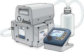 If you select ME4CVario, set the Pump Pressure Units to match the unit setting on the VARIO pump controller. The options are mbar, Torr, and hPa. |
Click Next.
8 Starts disassembled configuration only. Select the following:
a In the Location for Vacuum Filtration Collar list, select the deck location at which the collar is located, and then click Next.
b In the Vacuum Filtration Collar properties table, specify the following, and then click Next.
Pump | Description |
|---|---|
Collar type | Specify the size of the collar: Standard (38 mm) or Deep (67.5 mm). |
Black gasket on top side only | If the collar has the blue gasket or two black gaskets, select No (default). If you have omitted the black gasket on the underside of the collar, select Yes. |
9 Click Finish.
Note: If you verified the accuracy of the platepad teachpoint before installing and configuring the Vacuum Filtration Station, no further adjustment to the teachpoint should be required.
10 In the Profiles tab, click Update this profile.
11 VWorks Plus only. If an audit trail is being logged, the Audit Comment dialog box opens. Select or type the audit comment, and then click OK.
Testing the Vacuum Filtration Station
Before you start, ensure that you initialize the correct profile in Bravo Diagnostics.
Testing the Pump Standard option
If you selected the Standard connection option when configuring the Vacuum Filtration Station, use the following procedure to test the vacuum supply to the station.
To test the Standard connection for a Vacuum Filtration Station:
1 Verify that the pre-assembled Vacuum Filtration Station is in place on the target deck location and connected via the pinch-valve module.
2 In Diagnostics, click the Configuration tab.
3 In the Accessory Configuration area, highlight Vacuum Filtration Station, and then click Diagnose accessory.
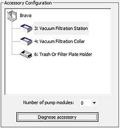 |
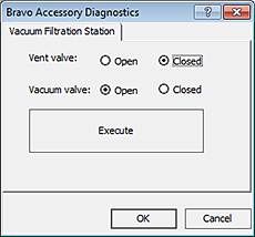
4 In the Accessory Diagnostics dialog box, start the vacuum as follows:
a Set the Vent valve to Closed.
b Set the Vacuum valve to Open.
c Click Execute.
Figure Accessory Diagnostics dialog box for the Standard connection
 |
5 To stop the vacuum:
a Set the Vent valve to Open.
b Set the Vacuum valve to Closed.
c Click Execute.
6 Click OK.
Configuring the ME4C NT VARIO Vacuum Pump and testing the vacuum
If you selected the ME4C Vario connection when configuring the Vacuum Filtration Station, use the following procedure to configure the pump settings and test the vacuum supply to the station.
For more details on the ME4C NT VARIO Vacuum Pump, see the manufacturer’s user guide.
To configure the ME4C NT VARIO Vacuum Pump and test the station:
1 Verify that the pre-assembled Vacuum Filtration Station is in place on the target deck location and connected to the VARIO Vacuum Pump.
2 In Diagnostics, click the Configuration tab.
3 In the Accessory Configuration area, highlight Vacuum Filtration Station, and then click Diagnose accessory.
|
The Accessory Diagnostics dialog box opens.
Figure Accessory Diagnostics dialog box for the ME4C NT VARIO Vacuum Pump
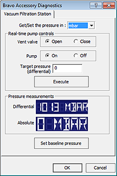 |
4 To configure the pump:
a In the Get/Set the pressure in list, select the desired unit of measure (mbar, Torr, hPa, mmHg, cmHg, and inHg). If the selected units differ from the configuration, the software will convert the values.
b Set the Vent valve to Open.
c Set the Pump to Off.
d Type the Target pressure (differential).
e Click Set baseline pressure.
5 To start the vacuum:
a Set the Vent valve to Close.
b Set the Pump to On.
c Set the Target pressure.
d Click Execute.
6 To stop the vacuum:
a Set the Vent valve to Open.
b Set the Pump to Off.
c Click Execute.
Related information
For information about... | See... |
|---|---|
Creating or updating labware definitions for filter and collection plates used with the Vacuum Filtration Station, including specifying the gripper offset | VWorks Automation Control Setup Guide |
The protocol liquid-handling tasks for the Vacuum Filtration Station | VWorks Automation Control User Guide |