Hardware overview
About this topic
This topic describes the following Labware MiniHub features:
Main components
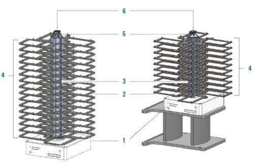
The following figure and table describe the main components of the Labware MiniHub.
Figure Main components: Integration Configuration (left) and BenchCel Configuration (right)
 |
Item | Name | Description |
|---|---|---|
1 | Base | White structure at the bottom of the Labware MiniHub that attaches the device to the target surface. The base contains the electronics and hosts the connection panel and the status lights. For the BenchCel Configuration, the Labware MiniHub base attaches to an integration-plate assembly (iKit). Typically, the integration-plate is on risers, as the figure shows, for integration with the BenchCel device on risers. However, if the BenchCel device is not on risers, the Labware MiniHub cannot be on risers. |
2 | Shelves | Flat area on which you can place labware. Locating pins at the edges of the shelves hold the labware securely in place. |
3 | Spacers | Metal spacing blocks that you can add to or remove from the center rod of the Labware MiniHub to adjust the distance between shelves. Two types of spacers are available: • 25.1-mm spacers. Stacked between shelves to accommodate different labware heights. • 8.4-mm spacers. Stacked above the top-most shelf to fill the space between the top-most 25.1-mm spacer and the cassette cap. These spacers ensure a tight assembly and are only necessary when a subset of the shelves are used. |
4 | Cassettes | Columns of shelves. The Labware MiniHub consists of four cassettes, each identified by the number on the cassette cap. |
5 | Cassette cap | Metal label with numerical identification of each cassette. The numbers are used in the VWorks software and in Labware MiniHub Diagnostics. |
6 | Black knob | Component at the top of the Labware MiniHub that locks the spacers and shelves in place. |
Power supply
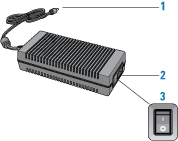
The power supply is the component that supplies electrical power to the Labware MiniHub.
Figure Power supply
 |
Item | Name | Description |
|---|---|---|
1 | Labware MiniHub cable connector | Connects the Labware MiniHub to the power supply unit. |
2 | Power inlet | Connects the power supply unit to the power source. Use only the supplied power cord. |
3 | On/off switch | Turns on (I) and off (o) the power supply. |
Status lights
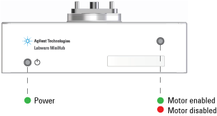
At the base of the Labware MiniHub are two indicator lights, as the following figure shows.
 |
Indicator light | Description |
|---|---|
Power | Indicates whether the power is on or off. When the green light is on, the power is on. When the green light is off, the power is off. |
Status | Indicates whether the motor is enabled or disabled. • Red light indicates the motor is disabled. • Green light indicates that the motor is enabled. |
Related information
For information about... | See... |
|---|---|
Labware MiniHub description | |
Labware MiniHub safety | |
Software overview |