Pin Tool (Agilent Bravo)
Description
The Pin Tool (Agilent Bravo) ( ) task can be used to perform low-volume transfers of a fixed volume using a pin tool. You can use the Pin Tool task repeatedly in a protocol subprocess to perform all the pin-tool-related steps, such as:
) task can be used to perform low-volume transfers of a fixed volume using a pin tool. You can use the Pin Tool task repeatedly in a protocol subprocess to perform all the pin-tool-related steps, such as:• Pin Tool—Adsorb
• Pin Tool—Dispense
• Pin Tool—Wash
• Pin Tool—Blot
• Pin Tool—Mix
Task is available for... | Task is available in... |
|---|---|
Bravo Platform | Main Protocol, Bravo Subprocess |
Before you begin
Ensure the following:
• The Bravo device profile specifies an appropriate pin tool. To create or edit a profile, see the user guide for the applicable device.
Note: Ensure the pin tool teachpoints are set up in the same manner as a fixed-tip pipette head.
• The protocol includes the SubProcess (Bravo).
Task parameters
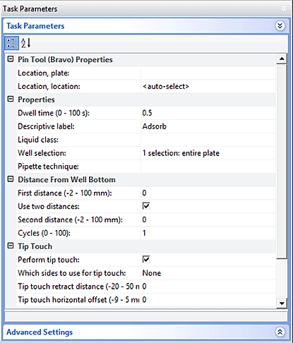
After adding the Pin Tool task at the desired point in the subprocess, set the following parameters in the Task Parameters area:
 |
Parameter | Description |
|---|---|
Location, plate | The labware involved in the Pin Tool task. |
Location, location | The location at which the Pin Tool task occurs. <auto-select> automatically places the labware at the first-available or appropriate location for the task. If accessories are installed on the deck or shelf, the software uses the accessory configuration information in Bravo Diagnostics or Vertical Pipetting Station Diagnostics to determine the correct location for the task. |
Dwell time (s) | The time duration that the pins remain at the specified height (First distance or Second distance) within the well. For example, you might start with the following values: • Adsorb, Dispense into fluid, or Mix—0.5 s or longer for more viscous fluids • Blot—2 s, or longer for more viscous fluids |
Descriptive label | A text label that you can add to the task icon in the protocol. Click the arrow in the Descriptive label box to choose an option. The options include: • Enter a JavaScript variable or script. • Use a predefined label: Adsorb, Dispense, Wash, Blot, or Mix • Type your own label in the box. |
Liquid class | A parameter that you can use to control the accuracy and the speed of the pin tool as it moves into and out of the wells. |
Well selection | The wells at which the Pin Tool task occurs. Use this parameter only if the pin tool has fewer pins than the number of wells in the microplate, for example, a 96-pin pin tool and a 384-well microplate. Click in the parameter box, and then click the Browse button to select the wells in the Well Selection dialog box. |
Pipette technique | The pipette location offset you want to use for the Pin Tool task. The list of pipette techniques are defined in the Pipette Technique Editor. |
First distance (mm) | The first height for the pin tool during the Pin Tool task. The value is the distance between the pin tips and the well bottoms. For example, during an adsorb step, you might set this value to 0 mm so that the pin tips touch the bottom of the wells. This parameter can affect the quantity adsorbed. |
Use two distances | The option to specify a second height for the pins during the Pin Tool task. For example, you could cycle the pin positions between two heights within the wells repeatedly to perform mixing or to wash the pins. Default: Not selected |
Second distance (mm) | The distance between the pin tips and the well bottoms at the second height for the pins. |
Cycles | Available if you select the Use two distances option. The Cycles parameter sets the number of times to move the pins repeatedly to the two heights, for example to perform mixing or to wash the pins. |
Perform tip touch | The option to touch the pins on one or more sides of the well, or to enable the pins to make lateral stirring moves inside the fluid, for example during a wash task. |
Which sides to use for tip touch | The side or sides of the well to use during tip touch: North, South, East, West, North/South, West/East, West/East/South/North. |
Tip touch retract distance (mm) | The vertical distance for the pins to move before moving laterally within the well, where • 0 is the vertical distance equal to the well bottom • > 0 is the vertical distance the pins rise above the bottom • < 0 is the vertical distance the pins attempt to move past the well bottom |
Tip touch horizontal offset (mm) | The horizontal distance that the pins move. The value is based on the well diameter specified by the labware definition, where • 0 is a distance equal to the well radius • > 0 is the distance the pins attempt to move past the well radius, which results in a more forceful tip touch • < 0 is a distance less than the radius of the well, resulting in a lighter tip touch or no tip touch |
Quadrant pattern well selection
A quadrant is an evenly spaced array of locations that are accessible by the tips on a pipette head. The following table lists the types of pipette heads and the number of accessible quadrants in various microplates.
Pipette head channels/pin tool pins | Microplate | Number of quadrants |
|---|---|---|
96 | 96-well 384-well 1536-well | 1 4 16 |
384 | 384-well 1536-well | 1 4 |
1536 (pin tool only) | 1536-well | 1 |
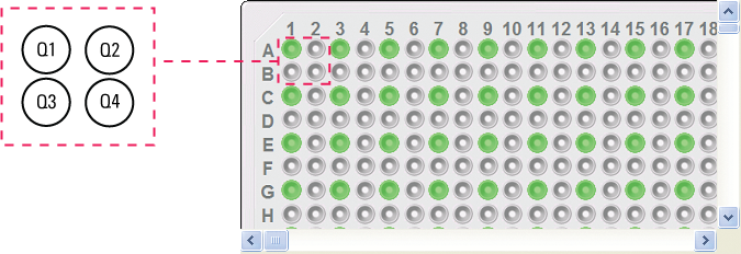
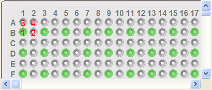
The following diagram demonstrates the concept of quadrants. The diagram shows a portion of a 384-well microplate and highlights the four quadrants (Q1, Q2, Q3, and Q4) that are accessible by the A1 tip of a 96-channel pipette head. Notice that the green color highlights all of the quadrant 1 (Q1) wells across the microplate.
 |
Instead of a column- or row-wise pattern, you can select a quadrant pattern during well selection.
The quadrant pattern option is available only if:
• The number of channels in the pipette head (or pins in a pin tool) is fewer than the number of wells in the microplate. For example, you can use a 96-channel pipette head to dispense liquid into a 384-well microplate or 1536-well microplate.
• All the channels are selected in the Set Head Mode task when using a pipette head. (The Set Head Mode task is not an option when using a pin tool).
• The liquid-handling task is inside a loop.
To select a quadrant pattern:
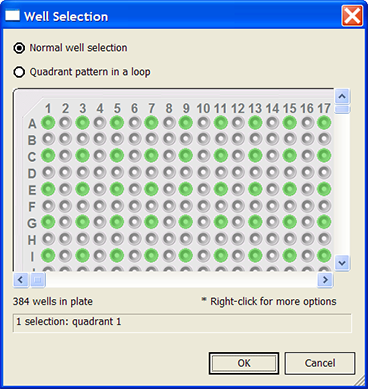
1 In the Task Parameters area, click the Well selection parameter box, and then click the Browse button. The Well Selection dialog box opens. By default, the Normal well selection option is selected. This option is used for column- and row-wise liquid-handling patterns.
 |
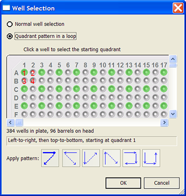
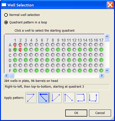
2 Select Quadrant pattern in a loop. The contents of the dialog box change. Notice the following:
• Red numbers (1 through 4) appear on wells A1, A2, B1, and B2. The numbers indicate the pipetting sequence: 1 is the starting well, and 4 is the last well. In the following example, the sequence is A1, A2, B1, B2.
• Green wells indicate the starting well in the pipetting sequence.
• Pattern buttons at the bottom of the dialog box indicate the movement of the pipette channels. The movement description is provided in the text box above the buttons.
Note: The last two patterns are unavailable if a group contains 16 wells. For example, the last two patterns are not available if you have a 96-well pipette head and a 1536-well microplate.
 |
3 Select the starting well. The well becomes green and is labeled 1.
In the following example, the third quadrant (B1 well) is selected.
 |
4 Click a pattern button to specify the pipette channel movement. After you click a pattern, the red numbers in the graphic are updated to show the sequence.
In the following example, the second pattern is selected (right-to-left, then top-to-bottom). The third quadrant (B1) is the starting well. The resulting movement is:
Quadrant 3 (B1)
Quadrant 2 (A2)
Quadrant 1 (A1)
Quadrant 4 (B2)
 |
5 When you are finished, click OK to save the changes and return to the VWorks window.
Example: Pin Tool tasks on a Bravo Platform
Goal
Using a pin tool, transfer a small volume from a source microplate (Source 1) into a destination microplate, and wash and blot the pins.
Implementation
The Bravo Platform is physically set up as follows:
• The source microplate is on deck location 3.
• The destination microplate is on deck location 6.
• The wash station is on deck location 1.
• The blotting material is on deck location 5.
In the protocol, the following are added:
• Process for the destination microplate
• Configured labware for the source microplate
• Configured labware for the wash station
• Configured labware for the blotting station
In the process, a Bravo subprocess is added. Within the subprocess, four Pin Tool tasks are added for Adsorb, Dispense, Wash, and Blot.
I
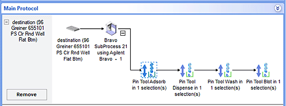 |
Parameter settings for each Pin Tool task in the example
• Adsorb
– Dwell time 0.5 s
– First distance 0 mm
– Second distance 10 mm
– Cycles 3
– No tip touch
• Dispense (into dry microplate)
– Dwell time 0.5 s
– First distance –2 mm
– No second distance
– No tip touch
• Wash
– Dwell time 0.5 s
– First distance 0 mm
– Second distance 10 mm
– Cycles 3
– Perform tip-touch on all sides with horizontal offset of 0 mm and at a retract distance of 2 mm
• Blot
– Dwell time 2 s
– First distance –2 mm
– No second distance
– No tip touch
Related information
For information about... | See... |
|---|---|
Adding devices | • Device user guide |
Adding tasks in a protocol | |
Liquid classes | |
Set Head Mode task | |
Microplate-handling tasks | |
Microplate-storage tasks | |
Scheduling tasks |