Reagent Transfer v3.0 User Guide
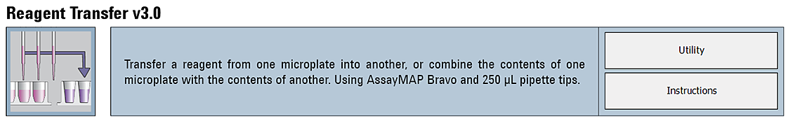
The Reagent Transfer v3.0 utility transfers samples or reagents from a Source Plate to a Destination Plate. This utility is useful for a wide variety of sample manipulation and reagent preparation operations. The utility features include the ability to:
• Conduct liquid transfers using either the bare probes of the AssayMAP head or 250-µL pipette tips.
• Control the liquid-handling processes, including:
– Use reverse pipetting or forward pipetting modes, which can increase pipetting accuracy depending on the liquid properties and volume being transferred.
– Select from a list of liquid classes or enter a custom liquid class.
– Specify whether to conduct syringe drying cycles and pre-wet cycles.
• Control the locations of the liquid transfer in both the Source and Destination plates.
Before you start
Labware
The following table provides a complete list of labware options and the corresponding deck locations for the Source Plate and Destination Plate.
The following figure shows the nine Bravo deck locations for labware.
Figure Labware locations on the Bravo deck (top view)
Labware options for deck locations 7 and 8 | Manufacturer part number* | Source Plate volume overage (well)** |
|---|---|---|
96 Eppendorf 30129300, PCR, Full Skirt, PolyPro | Eppendorf 30129300 | 10 µL |
96 Bio-Rad PCR, Hard-Shell, Low-Profile, Full Skirt | Bio-Rad HSP‑9611 | 10 µL |
96 Greiner 652270, PCR, Full Skirt, PolyPro | Greiner 652270 | 10 µL |
96 ABgene 1127, 1mL Deep Well, Square Well, Round Bottom | ABgene AB-1127 | 30 µL |
96 Greiner 650201_U-Bottom, Clear PolyPro | Greiner 650201 | 20 µL |
96 Greiner 650207_U-Bottom, White PolyPro | Greiner 650207 | 20 µL |
96 Greiner 651201_V-Bottom, Clear PolyPro | Greiner 651201 | 20 µL |
96 Costar 3363, PP Conical Bottom | Corning Costar 3363 | 20 µL |
96 Greiner 675801, Half Area, Flat-Bottom, UV Star | Greiner 675801 | 25 µL |
12 Column, Low Profile Reservoir, Natural PP | Agilent 201280-100 | 3 mL |
8 Row, Low Profile Reservoir, Natural PP | Agilent 201282-100 | 4.5 mL |
Reservoir, Seahorse 201254-100, PP, no walls, pyramid bottom | Agilent 201254-100 | 20 mL |
Reservoir, Axygen Scientific RES-SW96-LP, 86mL pyramid bottom | Axygen Scientific RES‑SW96‑LP | 20 mL |
96 V11 Manual Fill Reservoir | Agilent G5498B#049 | 35 mL |
96AM Receiver Plate | Included with Agilent cartridge rack | Not applicable |
96 Eppendorf 96-500 V-bottom, Clear, PolyPro*** | Eppendorf 96/500 | 25 µL |
96 Eppendorf 96-1000 U-bottom, Clear, PolyPro*** | Eppendorf 96/1000 | 25 µL |
96 Waters 186005837, Clear PolyPro*** | Waters 186005837 | 30 µL |
*For dimensionally equivalent alternatives, see the Labware Reference Guide in the Literature Library page of the Protein Sample Prep Workbench. **This overage does not include the volume required for reverse pipetting. The volume is listed by well, where a well is defined as an individual well in a 96-well plate. But in labware where multiple syringes can draw from a common source, a well is defined as that common source. For example, a 12-Column Low-Profile Reservoir has 12 wells, an 8-Row Low-Profile PolyPro Reservoir has 8 wells, and a Seahorse 201254-100, PP, No Walls, Pyramid-bottom Reservoir has only 1 well. ***Pipette tips are required for reagent transfers using these deep-well plate options. | ||
Experiment ID and method requirements
Each workbench application and utility has an Experiment Settings section that allows you to select an experiment ID and a method.
• An experiment ID is a database record that captures the steps executed and the settings used during each run of an application or utility. Any errors that may have occurred during a run are also recorded.
To create an experiment ID, you open the Experiments Editor by clicking  in any Workbench app or utility. For details, go to the Literature Library and open Using the Protein Sample Prep Workbench. In the browser that opens, click Using Experiment IDs.
in any Workbench app or utility. For details, go to the Literature Library and open Using the Protein Sample Prep Workbench. In the browser that opens, click Using Experiment IDs.• A method is a comprehensive collection of saved settings for an application or utility, which you can use to run the application or utility.
Experiment IDs and methods are required for compliance-enabled VWorks editions and optional for noncompliance-enabled VWorks editions.
VWorks edition | Experiment ID and method selection |
|---|---|
VWorks Plus | Required |
VWorks Standard | Optional |
Setting up the protocol
Before starting the protocol, make sure the appropriate selections and values are specified in the Reagent Transfer utility.
To set up the protocol:
1 Open the Utility Library.
2 Locate Reagent Transfer, and then click Utility.
 |
The Reagent Transfer utility opens.
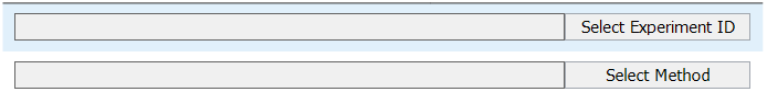
3 If applicable, click Select Experiment ID.
 |
The Experiments Editor opens.
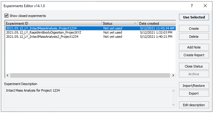 |
4 Select the Experiment ID that you want to use to record the steps performed during this application run, and then click Use Selected.
The Experiments Editor closes.
5 In the form, click Select Method to locate and select a method.
In the Open File dialog box, select the method, and click Open.
• To run the selected method, go to Starting the Reagent Transfer run.
• To create or modify a method, proceed to step 6.
VWorks Plus. Administrator or technician privileges are required to create and modify methods.
6 In the Application Settings area, specify the following settings for the run:
a Specify the Pipette Tip Settings.
Pipette Tip Setting | Description |
|---|---|
Use Pipette Tips | The option to use 250 µL pipette tips to transfer the liquid: • To use pipette tips, select the check box. • To use the bare probes on the AssayMAP head, clear the check box. Note: Ensure that the labware selection is appropriate for the bare probes. For details, see Before you start. Default: Not selected |
Transfer Pipette Tips from Deck Location 6 | If the Use Pipette Tips check box is selected, specify whether to transfer pipette tips using the Reagent Transfer utility. • To transfer the pipette tips from a source tip box at deck location 6 to the empty seating station at deck location 2, select the check box. • To use pipette tips that are already present in the seating station at deck location 2, clear the check box. For example, if you do a run and transfer the pipette tips from deck location 2 to the seating station, and then want to do additional runs with the same settings, the pipette tips can be reused. Default: Not selected |
Columns of Pipette Tips at Deck Location 6 | If the Transfer Pipette Tips from Deck Location 6 check box is selected, specify the range of full columns of pipette tips present in the source tip box (deck location 6) at the beginning of the run: • Left field is the first column that contains tips. • Right field is the last column that contains tips. For example: • For a full tip box: left field = 1, right field = 12 • For partially filled tip box with tips in columns 6 - 10: left field = 6, right field = 10 Default: 1 to 12 Range: • Starting column: 1–12 • Ending column: 1–12 |
b Specify the Source Plate Settings.
Source Plate Setting | Description |
|---|---|
Columns of Samples to Transfer | The range of wells (full columns) in the Source Plate (deck location 7) to be used for the reagent transfer. Note: If using bare probes, use the default range of 1 to 12. When using bare probes, the head moves as if it is moving all 96 positions from the Source Plate to the Destination Plate. Therefore, liquid will be moved from every position on the Source Plate where it exists to every corresponding position on the Destination Plate. Default: 1 to 12 Range: • Starting column: 1–12 • Ending column: 1–12 |
Initial Well Volume | The volume of liquid present in the wells of the Source Plate (deck location 7) before transferring the liquid. For labware where multiple syringes draw from a common source, a “well” is defined as that common source. For example, a 12-Column Low-Profile Reservoir has 12 wells, an 8-Row Low-Profile PolyPro Reservoir has 8 wells, and a Seahorse 201254-100, PP, No Walls, Pyramid-bottom Reservoir has only 1 well. For these labware types, the Initial Well Volume is calculated as:  For example, in the Seahorse 201254-100, PP, No Walls, Pyramid-bottom Reservoir the overage required is 20 mL plus 96 times the volume to be transferred (e.g., 100 µL) divided by 96:  This value is used to calculate the appropriate height for the pipette tips or probes during the aspiration process, and to facilitate proper dynamic-tip behavior. Note: Using a value of 0 will disable dynamic-tip movement and force the probes or tips to aspirate from the minimum distance from the well bottom of the selected labware. This might result in the pipette tip or probe exterior being exposed to liquid that might not be removed at the wash station. Default: 0 (µL) Range: 0–1500 (µL) |
Volume to Transfer | The volume of liquid per syringe to transfer from the Source Plate (deck location 7) to the Destination Plate (deck location 8). If this volume setting is greater than the capacity of the probes or pipette tips, the transfer will be evenly split into multiple aspirate-and-dispense cycles. Default: 10 (µL) Range: 0–1200 (µL) Note: The Automatic Liquid Class setting is designed for a 5 µL minimum. A volume less than 5 µL might require a custom liquid class. Note: A value of 0 will drive the probes or tips to the minimum height within the wells and keep them there for the duration of the aspiration step. |
c Specify the Destination Plate Settings.
Destination Plate Setting | Description |
|---|---|
Columns to Receive Samples | The range of full columns in the Destination Plate (deck location 8) to which the samples will be transferred. When using pipette tips, this range can differ from the range specified for the Columns of Samples to Transfer value, but it must contain the same number of full columns. If not, the software displays an error message, and the protocol automatically aborts. When using bare probes, use the default range of 1 to 12. The AssayMAP Bravo head moves as if it is transferring liquid from all 96 wells. The wells that contain liquid dictate which wells are transferred. Default: 1 to 12 Range: • Starting column: 1–12 • Ending column: 1–12 |
Initial Well Volume | The volume of liquid present in each well of the Destination Plate (deck location 7) before starting the transfer. Note: A well is defined as an individual well in a 96-well plate. But in labware where multiple probes can pull from the same continuous liquid source, a well is defined as that continuous liquid source. For example, a 12-Column Low-Profile Reservoir has 12 wells, an 8-Row Low-Profile PolyPro Reservoir has 8 wells, and a Seahorse 201254-100, PP, No Walls, Pyramid-bottom Reservoir has only 1 well. This value is used to calculate the appropriate height for the pipette tips or probes during the transfer dispense process, and to facilitate proper dynamic tip behavior. Default: 0 (µL) Range: 0–1500 (µL) |
Mix Cycles after Transfer | The number of aspirate-and-dispense cycles used to mix the contents of the Destination Plate (deck location 8) after the transfer has been completed. The volume used for the mixing process is automatically calculated based on practical low-volume pipetting limits and maximum syringe or probe volume capacities. Default: 0 Range: 0–20 Mixing formula: If (x – 50 µL) > Syringe/Tip Capacity, then Mixing Volume = Syringe/Tip Capacity If 50 µL ≤ x ≤ Syringe/Tip Capacity, then Mixing Volume = 0.75x If x < 50 µL, then Mixing Volume = 0.5x where, x is the final volume in the destination wells, maximum Syringe Capacity = 250µL, maximum Tip Capacity = 140µL Note: Syringe and pipette tip capacities vary depending on the Blowout Volume setting. |
d Specify the Wash Settings.
Wash Setting | Description |
|---|---|
Initial Syringe/Tip Wash Cycles | The number of syringe or pipette tip wash cycles to be performed at the wash station (deck location 1) before starting the reagent transfer portions of the run. Default: 0 Range: 0–10 |
Final Syringe/Tip Wash Cycles | The number of syringe or pipette tip wash cycles to be performed at the wash station (deck location 1) after completing the reagent transfer portions of the run. Default: 0 Range: 0–10 |
e Specify the Liquid Handling Preferences.
Liquid Handling Setting | Description |
|---|---|
Syringe Drying Cycles | The number of syringe purge cycles to be conducted with air before starting the run. This step occurs at different times for runs that use pipette tips instead of probes. • If using pipette tips. This step occurs before the Initial Wash cycles. • If using bare probes. This step occurs after the Initial Wash Cycles are completed. Default: 2 Range: 0–5 |
Pre-Wet Cycles | The number of times to wet the probes or pipette tips with the liquid from the Source Plate (deck location 7) before starting the transfer process. Note: Prewetting the pipette tips is a common pipetting technique that can greatly increase accuracy in certain situations. Default: 0 Range: 0–5 |
Reverse-Pipetting Overage | Specifies whether to run in reverse pipetting mode, and if so, the volume to be added to the volume that is being transferred. • To specify forward pipetting mode. Use the default setting of 0 µL. • To specify reverse pipetting mode. Use a value that is greater than 0 µL, and select the discard location for the extra liquid. This extra liquid remains in the pipette tips or probes for the entire reagent transfer process. Before conducting the mix cycles after the transfer, the excess volume is discarded to the Source Plate (deck location 7) or to Wash Station Waste (deck location 1), depending your selection. Note: Reverse pipetting is a common pipetting technique that can greatly increase accuracy in certain situations. Default: 0 (µL) Range: 0–50 (µL) |
Blowout Volume | The volume of air to dispense out of the syringes or pipette tips after completing the liquid transfer steps. The blowout process is different for the reverse-pipetting and forward-pipetting modes because of the presence of the Reverse-Pipetting Overage volume. • Forward pipetting mode. The blowout occurs after the transfer has completed, and then again after mixing, if conducted. • Reverse pipetting mode. The blowout occurs only after the mixing step, if conducted, because of the presence of the Reverse-Pipetting Overage volume. Default: 0 (µL) Range: 0–50 (µL) |
Liquid Class | The pipetting speed and accuracy. To ensure consistent pipetting, always select a liquid class for liquid-handling tasks. Choose from the following options: • <Automatic> (default). Automatically assigns one of the following liquid classes, based on whether pipette tips are used and the volume being transferred. These are good general-purpose liquid classes for most reagents and buffers that are used for the AssayMAP system. – Bare probes: 0–20 µL (AM_ProbesLowVol) > 20 µL (AM_ProbesHighVol) – Pipette tips: 0–20 µL (AM_250uLTipsLowVol) > 20 µL (AM_250uLTipsHighVol) • Slow Flow (5 µL/sec). A slower flow rate is better for viscous solutions. • Fast Flow (100 µL/sec). A faster flow rate is a good starting point for high organic solutions. If these flow rates do not provide the desired performance, you may enter a custom liquid class. To create a custom liquid class, you use the VWorks Liquid Library Editor. For details on how to open the VWorks Liquid Library Editor, see Creating a custom liquid class. To enter a custom liquid class for the reagent transfer: In the Liquid Class box, type the liquid class name exactly as it appears in the VWorks Liquid Library Editor. |
f In the Labware Table, select that labware you are using at deck locations 7 and 8.
7 To save the method:
a Click  .
.
.b In the Save File As dialog box, type the file name and click Save.
VWorks Plus. You must save the method before you can run it.
Starting the Reagent Transfer run
To start the protocol run:
1 Ensure that the accessories and labware are at the assigned deck locations, as shown in the Deck Layout image of the form.
Make sure the labware are properly seated on the Bravo deck.
2 If the method specifies Use Pipette Tips, do one of the following:
• If the Transfer Pipette Tips from Deck Location 6 check box is selected, ensure that the:
– Pipette tip box containing the specified range of pipette tips is in position at deck location 6.
– Empty seating station is in place at deck location 2.
• If the Transfer Pipette Tips from Deck Location 6 check box is cleared, ensure that the seating station at deck location 2 contains the specified range of pipette tips.
Note: A message will appear and ask you to verify that the pipette tips are in the correct locations. Ensure that the pipette tips are arranged in the specified locations.
3 Click  to start the run.
to start the run. To monitor the progress of the run, check the Status box.
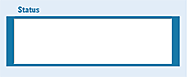 |
To pause the run, click Pause. The task currently in progress finishes before the protocol pauses. The Scheduler Paused dialog box opens. For details, see Emergency stops and pauses.
See the following section for guidance on how to handle error, warning, and verification messages. To troubleshoot errors, see the Error Recovery Guide and the Bravo Platform User Guide in the Literature Library page of the Protein Sample Prep Workbench.
Error, warning, and verification messages
Detected error in the setup
If the software detects a conflict in the setup, an error message or warning will appear before the run begins.
Figure Examples of error messages that prevent run execution
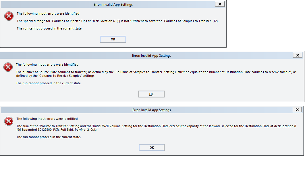 |
To resolve error messages about setup conflicts:
1 In the form, resolve the settings described in the error message, for example:
• Insufficient number of columns of pipette tips
• Unequal number of columns selected for Source and Destination plates
• Incompatible labware selections (labware that require pipette tips)
VWorks Plus. Administrator or technician privileges are required to create and modify methods.
2 To save the new method, click .
.In the Save File As dialog box, type the file name and click Save.
VWorks Plus. You must save the method before you can run it.
3 To select the new method, click Select Method.
In the Open File dialog box, select the new method, and click Open.
4 Click to start the run.
to start the run. Verification and warning messages
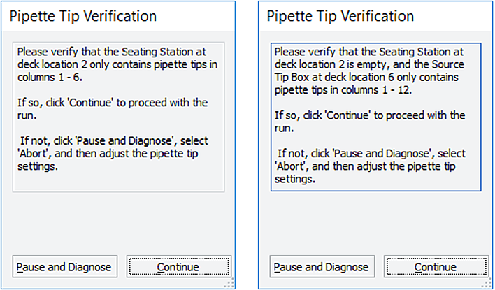
Verification and warning messages that appear allow you to continue with the run as specified, while assuming the risk posed by the warning. The following figure shows some examples.
Figure Examples of verification messages
 |
To resolve verification and warning messages:
Follow the on-screen instructions to verify that the settings are correct, and then do one of the following:
• If the settings are correct, click Continue to start the run.
Note: A Pipette Tip Verification message appears whenever pipette tips are used.
• If you need to change a setting:
VWorks Plus. Administrator or technician privileges are required to create and modify methods.
a Click Pause and Diagnose. The Scheduler Paused dialog box opens.
b In the Scheduler Paused dialog box, click Abort process.
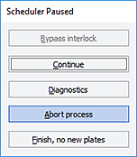 |
c In the form, change the settings to resolve the conflict.
VWorks Plus. Administrator or technician privileges are required to create and modify methods.
d To save the new method, click .
.In the Save File As dialog box, type the file name and click Save.
VWorks Plus. You must save the method before you can run it.
e To select the new method, click Select Method.
In the Open File dialog box, select the new method, and click Open.
f Click to start the run.
to start the run. Creating a custom liquid class
Administrator or technician privileges are required to create or modify liquid classes.
To create a custom liquid class:
1 In the Reagent Transfer v3.0 form, click Toggle Full Screen to change the display of the form so that the VWorks menubar and toolbar are visible, as the following figure shows.
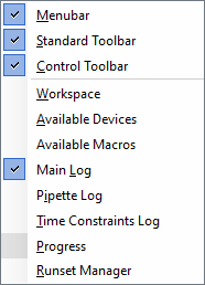
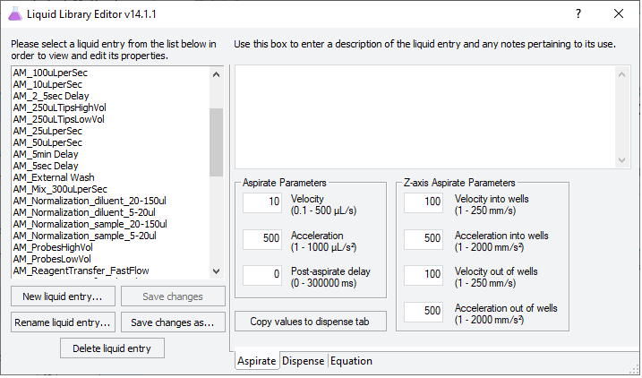
2 In the VWorks window, click Tools > Liquid Library Editor. The Liquid Library Editor opens.
If the menubar is not visible in the VWorks window, right-click the window and select Menubar in the shortcut menu that appears.
 |
3 For instructions on how to use the Liquid Library Editor, see the section on specifying pipette speed and accuracy in the VWorks Version 4 Automation Control Setup Guide in the VWorks Knowledge Base.
Figure VWorks Tools menu and form displayed with full screen off
 |
Figure VWorks Liquid Library Editor window
 |
Automation movements during the protocol
This section describes the basic movements of the AssayMAP Bravo Platform during the Reagent Transfer protocol using the default method settings. Changing the selections or parameters will alter the movements.
Protocol step | Head moves to deck location... | Action |
|---|---|---|
1 | 1 | Washes the syringes. If pipette tips are used for the transfer, this step occurs after step 3 below to facilitate pipette tip washing. |
2 | 1 | Purges the syringe contents to waste for the number of cycles set in the Syringe Drying Cycles setting. |
3 | 6 | If applicable, picks up the pipette tips from the source tip box. This step occurs only if the Use Pipette Tips check box and the Transfer Pipette Tips from Deck Location 6 check box are selected. |
2 | If applicable, ejects the pipette tips into the seating station. | |
4 | 2 | If applicable, picks up all the pipette tips from the seating station This step occurs only if the Use Pipette Tips check box is selected and the Transfer Pipette Tips from Deck Location 6 check box is cleared. A confirmation message verifies that the pipette tip locations are correct. |
5 | 7 | Aspirates and dispenses the liquid in the Source Plate to wet the pipette tips or syringe probes for the number of cycles set in the Pre-Wet Cycles setting. |
6 | 7 | Aspirates the volume to be transferred from the Source Plate using the pipette tips or syringe probes. |
7 | 8 | Dispenses the liquid into the Destination Plate. |
8 | 7 & 8 | Repeats steps 6 and 7 until the full volume specified in the Volume to Transfer setting has been transferred to the Destination Plate. Pipette tip maximum volume: ~140 µL can be pulled into a mounted tip before the excess fluid overflows into the syringe, because the probe protrudes into the tip volume capacity. Probe maximum volume: 250 µL can be aspirated into the syringe before the syringe is full. The probe maximum volume will be reduced automatically by an amount that is equal to the specified Blowout Volume. |
9 | 8 | Mixes the contents of the Destination Plate. |
10 | 8 | Performs a blowout slightly above the liquid level of the Destination Plate to clear any remaining liquid. |
11 | 8 | Performs a tip touch on the left and right sides of the wells in the Destination Plate. |
12 | 1 | Washes the pipette tips or syringe probes. |
13 | 2 | If pipette tips are used, ejects the pipette tips into the seating station |
14 | 1 | Moves the head above the wash station. |