Setting up a Reformatting method

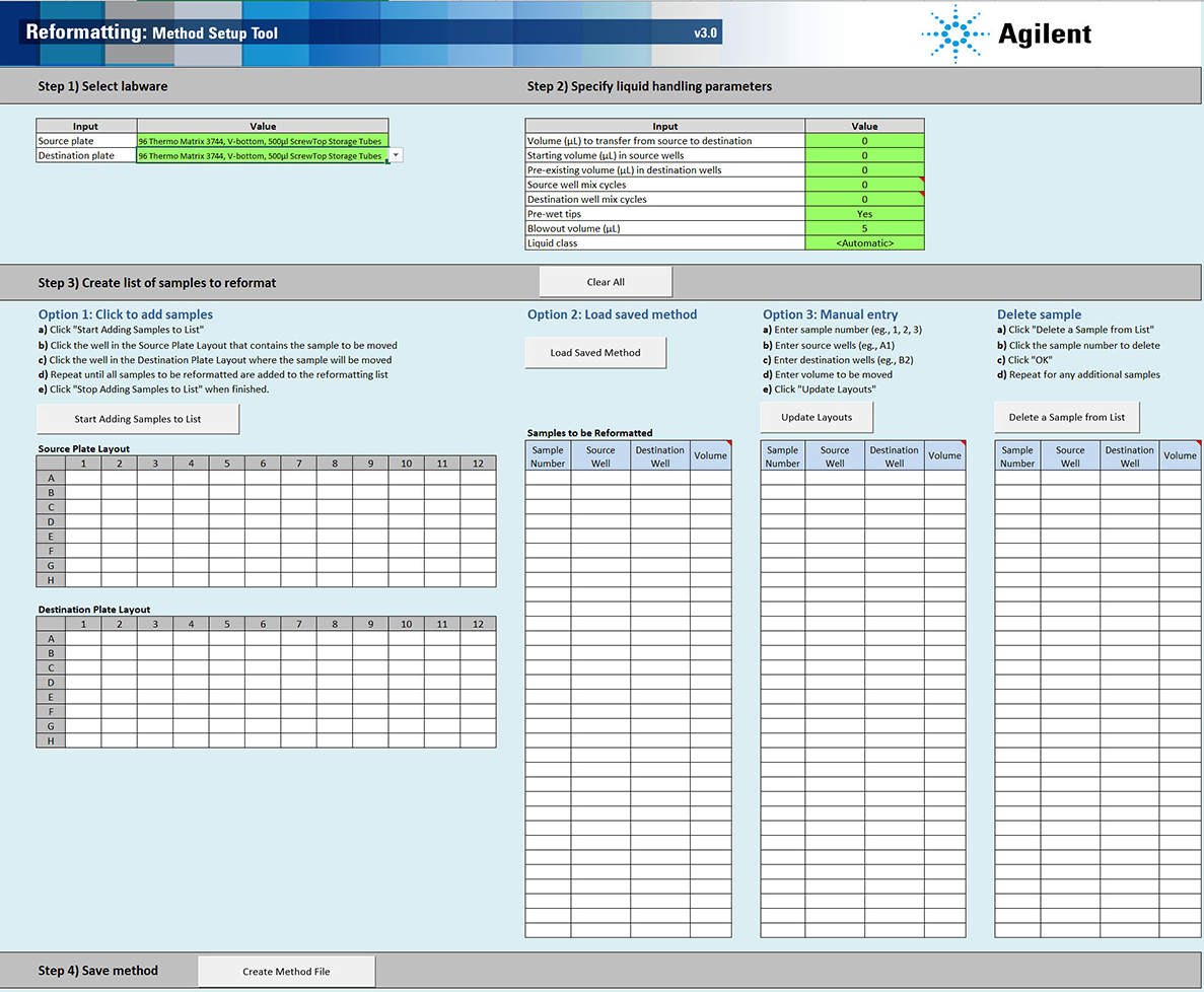
The Method Setup Tool is a Microsoft Excel-based tool that steps you through the process of creating and saving a method file that contains all the information required to run the Reformatting protocol on the AssayMAP Bravo Platform. This tool enables you to define the location of the samples to be transferred, the volumes to be transferred, and the liquid-handling parameters to be used.
Note: When you select a method in the Reformatting utility, the form displays the corresponding labware selections and source and destination plate instructions.
Figure Reformatting Method Setup Tool
 |
Opening the Method Setup Tool
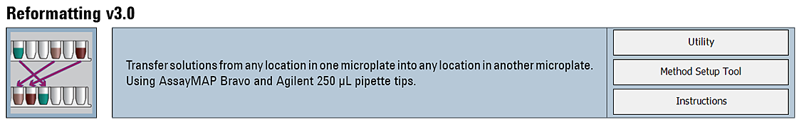
You can open the tool from the Utility Library or from the Reformatting form.
To open the Method Setup Tool:
1 In the Utility Library, locate the Reformatting banner.
 |
2 Click one of the following buttons:
• Method Setup Tool. Microsoft Excel starts and displays the Method Setup Tool.
• Utility. The Reformatting utility opens.
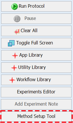
In the navigation pane, click Method Setup Tool. Microsoft Excel starts and displays the Method Setup Tool.
 |
Overview of steps in Method Setup Tool
The Method Setup Tool has 4 distinct steps. The following table provides an overview of the steps.
Table Overview of steps in Method Setup Tool
Step | Description | ||
|---|---|---|---|
1 | Select labware | Click the green Source plate box, and then select the labware to be placed on the plate riser at deck location 2. Click the green Destination plate box, and then select the labware to be placed on the plate riser at deck location 6 If multiple transfers will be pooled in a single destination well, ensure that the well has sufficient capacity. | |
2 | Specify liquid handling parameters | Enter values for the following inputs: | Default value (Range) |
Volume (µL) to transfer from source to destination Note: <5 µL is possible but the accuracy and precision starts to decrease below 5 µL. | 0 (5–1000) | ||
Starting volume (µL) in source wells | 0 (0–1000) | ||
Pre-existing volume (µL) in destination wells | 0 (0–995) | ||
Source well mix cycles Note: The number of mix cycles is dependent on the volume, viscosity, and size of molecules in the solution being mixed. | 0 (0–100) | ||
Destination well mix cycles If transferring from multiple source wells into a single destination well, additional off-deck mixing may be required because the mixing volume is based on a single transfer volume. | 0 (0–100) | ||
Pre-wet tips | Yes (No, Yes) | ||
Blowout volume (µL) | 5 (0–50) | ||
Liquid class | Automatic (presets or custom) | ||
3 | Create list of samples to reformat | Use one or a combination of the following options to create and edit the list of samples: • Option 1. Select the source and destination well locations for each sample on the plate maps. • Option 2. Load a saved method. Note: The saved method must be exported in order to use Option 2. • Option 3. Manually enter the source and destination locations for each sample in the sample table. | |
4 | Save method | Click Create Method File. The setup tool creates a comma-separated value (.csv) text file that you use to run the utility. | |
Step 1) Select labware
For the labware options at each deck location, see Labware.
To select the labware:
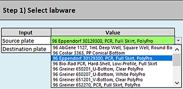
1 In the cell next to Source plate, select the labware that you are placing on the plate riser at deck location 2 as follows:
Click the green cell, and then click the arrow that appears. In the list, click the labware type to be used.
 |
2 In the cell next to Destination plate, select the labware that you are placing on the plate riser at deck location 6 as follows:
Click the green cell, and then click the arrow that appears. In the list, click the labware type to be used.
Step 2) Specify liquid handling parameters
Note: Only the cells highlighted in green are editable.
To specify the liquid handling parameters:
Type or select the values for the following inputs:
Input | Description |
|---|---|
Volume (µL) to transfer from source to destination | The volume to be aspirated from the specified well in the source plate and then dispensed in the specified well in the destination plate. Note: This value is automatically entered into the list of samples to be reformatted in step 3, option 1 of the Method Setup Tool. You can use step 3, option 3 to edit the volume on a sample-by-sample basis. Default: 0 (µL) Range: 5–1000 (µL) Note: Samples <5 µL are possible using step 3, option 3, but samples <5 µL may not have good accuracy or precision. |
Starting volume (µL) in source wells | The initial volume in each well of the source plate before the transfer starts. The software uses this volume for error checking and to calculate the liquid height in the wells to facilitate proper dynamic tip behavior. The software error checking assumes that the volume is the same in each well of the plate. If well volumes vary, enter the smallest volume as the Starting volume. By doing so, the error checking can alert you if you enter a value to be transferred that is larger than the initial volume. Also, you should enter the value for the smallest source well volume so as not to introduce bubbles while mixing. Note that the larger volume wells may not mix as well as the smaller volume wells because the mixing volume is based on the value on the Starting volume in source wells setting. If doing multiple transfers from a single source well, be sure to include enough volume as the error checking assumes only a single transfer. Including a volume overage. Be sure to include sufficient excess volume (dead volume) in the source well to ensure good accuracy and precision. For volume recommendations, see the Labware Reference Guide (workbench Literature Library page). The Starting volume in the source wells is the actual volume in the source well, which should equal the amount to be transferred plus the overage (dead volume). For 96 well plates, the Starting volume in the source wells setting is straightforward. For labware where multiple pipette tips can draw from a common source, the situation is more complex. The Starting volume is still the volume to be transferred plus the overage (dead volume) but the overage is not the overage for the entire common source. Instead, it is the overage for the common source divided by the number of virtual wells in that common source based on a 96 well plate map. • For example, a 12-Column Low-Profile Reservoir has 8 virtual wells per column so the overage used to calculate the Starting volume would be the recommended dead volume per column divided by 8. Similarly, an 8-Row Low-Profile Reservoir has 12 virtual wells per row so the overage used to calculate the Starting volume would be the dead volume per row divided by 12. • For a reformatting method where 50 µL is to be transferred per well with a 12‑Column Low-Profile Reservoir as the source plate, the starting volume should be: 3 mL / 8 = 375 µL + 50 µL = 425 µL Default: 0 (µL) Range: 0–1050 (µL) |
Pre-existing volume (µL) in destination wells | The initial volume in each well of the destination plate before the Reformatting utility is run. The software uses this volume for error checking, to calculate mixing volumes, and to calculate the liquid height in the wells to facilitate proper dynamic tip behavior. For 96 well plates, the Pre-existing volume in the destination wells is straightforward but for labware where multiple pipette tips can draw from a common source the situation is more complex. The Pre-existing volume is the total volume in the common source divided by the number of virtual wells in that common source, based on a 96-well plate map. For example, a 12-Column Low-Profile Reservoir has 8 virtual wells per column, so the Pre-existing volume would be the volume in the column divided by 8. Similarly, an 8-Row Low-Profile Reservoir has 12 virtual wells per row, so the Pre-existing volume would be the volume in the row divided by 12. Default: 0 (µL) Range: 0–995 (µL) |
Source well mix cycles | The number of aspirate-and-dispense cycles used to mix the contents of the wells in the source plate before the sample is aspirated. Mix cycles are not recommended if any of the source wells will be used multiple times, because the mixing calculation assumes the volume in the source well is the Starting volume (µL) in source wells value. Therefore, following the initial volume drawn, the mixing volume could be greater than the volume in the well, and the mixing could introduce bubbles. The software assumes that all the wells in the source plate have the same volume. If any well has less volume than the volume set in the Starting volume (µL) in source wells field, mixing could introduce bubbles. For additional details, see Automation movements and stepwise guidelines. Default: 0 Range: 0–100 |
Destination well mix cycles | The number of aspirate-and-dispense cycles used to mix the contents of the wells in the destination plate after the sample is transferred to the destination well. The mixing volume may be too low for destination wells that receive multiple transfers because the mixing volume calculation assumes that the volume in the destination well is a single transfer plus the Pre-existing volume (µL) in the destination wells. If your protocol includes multiple source well transfers into a single destination well, Agilent recommends using a shaker to perform additional mixing. For additional details, see Automation movements and stepwise guidelines. Default: 0 Range: 0–100 |
Pre-wet tips | The option to wet the pipette tips with the liquid from the source well before drawing liquid from the source well. Note: Prewetting pipette tips is a common pipetting technique that can increase accuracy and precision in certain situations. For additional details, see Automation movements and stepwise guidelines. Default: Yes Options: Yes, No |
Blowout volume (µL) | The volume of air to be drawn into the pipette tip before aspirating the sample. After dispensing the transferred sample, the volume of air remaining in the tip is dispensed (blown out) while the tip is still in the well. The blowout is followed by a tip touch on the east and west sides of the well. If the Blowout volume is set to 0, no blowout or tip touches will occur after the transfer is complete. For additional details, see Automation movements and stepwise guidelines. Default: 5 (µL) Range: 0–50 (µL) |
Liquid class | The pipetting parameters (for example, aspiration and dispense speeds). The liquid class selection strongly influences the pipetting precision and accuracy. This choice only controls the aspiration and dispense of the samples. The mixing speed of the dilutions is fixed at 300 µL/sec. Options: • <Automatic> (default). Automatically assigns one of the following liquid classes, based on the volume being transferred. 0–20 µL (AM_250uLTipsLowVol) > 20 µL (AM_250uLTipsHighVol) These are good general-purpose liquid classes for most reagents that are used with the AssayMAP system. • Slow Flow (5 µL/sec). A slower flow rate is better for viscous solutions. • Fast Flow (100 µL/sec). A faster flow rate may improve performance for high organic solutions. If these flow rates do not provide the desired performance, you may enter a custom liquid class. To create a custom liquid class, see To modify or create a custom liquid class:. To enter a custom liquid class: In the Liquid class box, type the liquid class name exactly as it appears in the VWorks Liquid Library Editor. Note: The estimated run time (Status box area) may not be accurate for methods that use a custom liquid class. |
Pipetting accuracy and liquid classes
Pipetting accuracy and precision can be greatly affected by liquid properties, such as viscosity and surface tension. If unacceptable accuracy and precision results are observed, you may modify these liquid classes to achieve acceptable results. Use the following procedure to modify or create a liquid class.
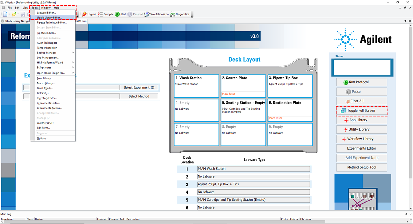
To modify or create a custom liquid class:
1 In the Reformatting form, click Toggle Full Screen to change the display of the form so that the VWorks menubar is visible.
Figure VWorks Tools menu and form displayed with full screen off
 |
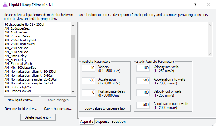
2 Click Tools > Liquid Library Editor. The Liquid Library Editor opens.
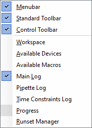
If the menubar is not visible in the window, right-click the window and select Menubar in the shortcut menu that appears.
 |
3 For instructions on how to use the Liquid Library Editor, see the section on specifying pipette speed and accuracy in the VWorks Automation Control Setup Guide.
Figure VWorks Liquid Library Editor window
 |
Step 3) Create list of samples to reformat
You can use any of the following options to create and edit the list of samples:
• Option 1. Click to add samples
• Option 2. Load saved method
A saved method must be exported before it is available to load in Option 2. For details on how to export a method, see Exporting and importing AssayMAP methods.
• Option 3. Manual entry
You can also use a combination of options. For example, you can enter some sample transfers using option 1 or 2 and then you can add additional sample transfers manually. If you do this, remember to click Update Layouts after you are done.
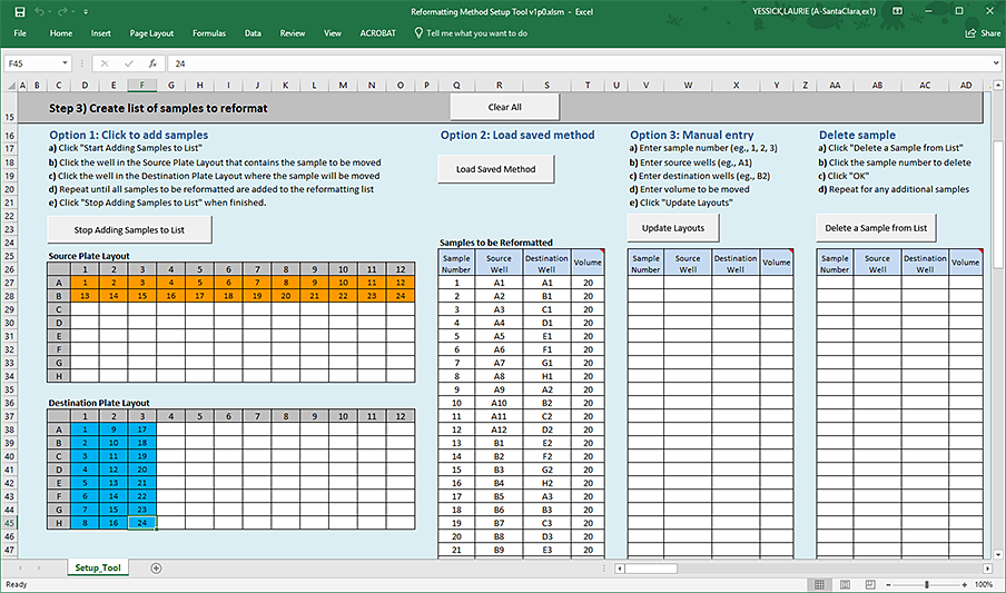
The added samples appear in the Samples to be Reformatted table and in the Source Plate Layout and Destination Plate Layout, as the following figure shows. You can use the manual entry method to modify the volumes in the Samples to be Reformatted table.
Note: The Method Setup Tool assigns consecutive sample numbers based on the sequence in which you add the samples.
 |
If necessary, you can delete samples from the list one at a time using the Delete sample feature. The Method Setup Tool consecutively renumbers the remaining samples in the list based on the sequence in which they were added.
To use the Click to add samples option:
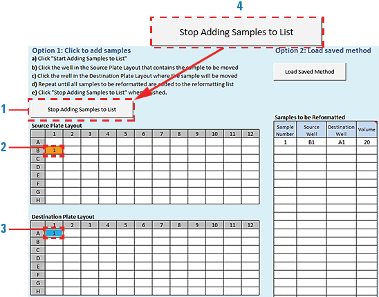
1 Click Start Adding Samples to List.
Note: The button label changes to Stop Adding Samples to List.
2 In the Source Plate Layout, click the well that contains the sample to be moved, and then click the well in the Destination Plate Layout where this sample will go.
As the figure shows, the cells change color in both plate layouts to designate the added samples. The corresponding sample and well designations appear in the Samples to be Reformatted table.
 |
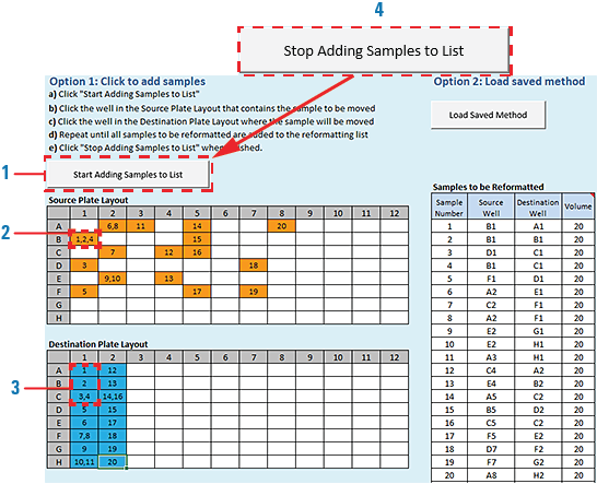
3 Repeat step 2 to add additional samples to the list.
• You can draw multiple times from the same source well. See B1 in the following source plate example.
• You can dispense multiple times in the same destination well. See C1, H1, and C2 in the following destination plate example.
4 When you are finished adding samples using Option 1, click Stop Adding Samples to List. See figure, item 4.
 |
To use the Load Saved Method option:
1 Make sure you have exported a saved method:
a Use the File > Export Misc File command in the VWorks window.
b Ensure that the method file to be exported is a Reformatting v3.0 method.
– VWorks Plus default storage location:
… /VWorks Projects/VWorks/AM Methods/AM Reformatting v3.0
… /VWorks Projects/VWorks/AM Methods/AM Reformatting v3.0
– VWorks Standard default storage location:
C:\OLSS Projects\VWorks Projects\VWorks\AM Methods\AM Reformatting v3.0
C:\OLSS Projects\VWorks Projects\VWorks\AM Methods\AM Reformatting v3.0
For details, see Exporting and importing AssayMAP methods.
2 If applicable, click Clear All to refresh the tables in the Method Setup Tool.
3 Click Load Saved Method.
a In the Open dialog box, select the exported method file (*.csv), and then click Open.
b The samples appear in the Source Plate Layout, Destination Plate Layout, and Samples to be Reformatted table.
To use the Manual entry option:
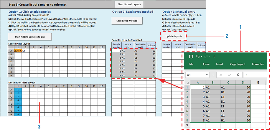
1 Type or copy-and-paste the required information in the Samples to be Reformatted table.
Note: You can edit volumes that you entered using options 1 or 2. If the volume in the Samples to be Reformatted table has been modified so that it does not equal the volume set in Step 2, the corresponding cell turns yellow in the table. The yellow highlight is only a caution for you to verify that these values are intended.
If you are copying rows from a table, ensure the content of the cells matches the column order of the Samples to be Reformatted table. See the following figure, item 1.
2 Click Update Layouts to populate the sample information in the Source Plate Layout and Destination Plate Layout (figure, item 2).
3 Notice that the cells change color in both plate layouts to designate the added samples (figure, item 3).
 |
To delete a sample from the list:
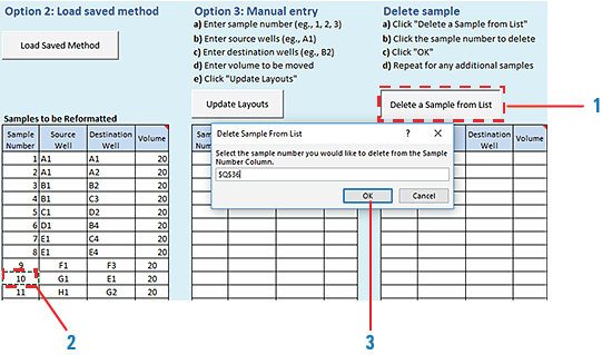
1 Click Delete a Sample from List. See figure, item 1.
The Delete Sample From List dialog box opens.
2 In the Samples to be Reformatted table, click the cell in the Sample Number column (figure, item 2).
Note: Samples can be deleted only one at a time.
3 Click OK in the Delete Sample From List dialog box (figure, item 3).
The software updates the Samples to be Reformatted table and the plate layouts. If you delete a sample that is not at the end of the list, the software renumbers the samples remaining in the list in consecutive order.
 |
Step 4) Save method
To save the reformatting method:
1 Click  .
.
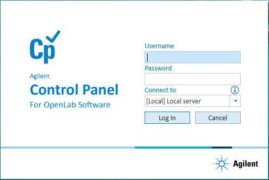
.2 In the login window, type your VWorks user name and password, and click Log In.
 |
3 In the Save File dialog box, specify the file name and the storage location, and then click Save.
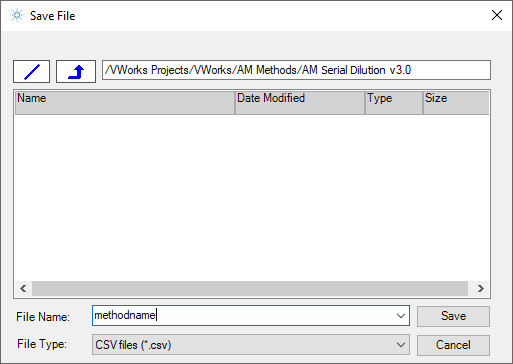 |
• VWorks Plus default storage location:
… /VWorks Projects/VWorks/AM Methods/AM Reformatting v3.0
… /VWorks Projects/VWorks/AM Methods/AM Reformatting v3.0
• VWorks Standard default storage location:
C:\OLSS Projects\VWorks Projects\VWorks\AM Methods\AM Reformatting v3.0
C:\OLSS Projects\VWorks Projects\VWorks\AM Methods\AM Reformatting v3.0
Note: The method file is stored as a record of interest (ROI) in an archive (.csv.roiZip). VWorks cannot load files (.roiZip extension) that have been modified or renamed outside of the Protein Sample Prep Workbench or VWorks software.
4 Click OK when the uploaded successfully message appears. The Method Setup Tool closes.
 |
To display the method’s labware selections and preparation instructions do one of the following:
• Open the Reformatting utility and select the method. For details, see Running the protocol.
• Export the method and view it in Microsoft Excel. For details, see Exporting and importing AssayMAP methods.