Setting up a Serial Dilution method

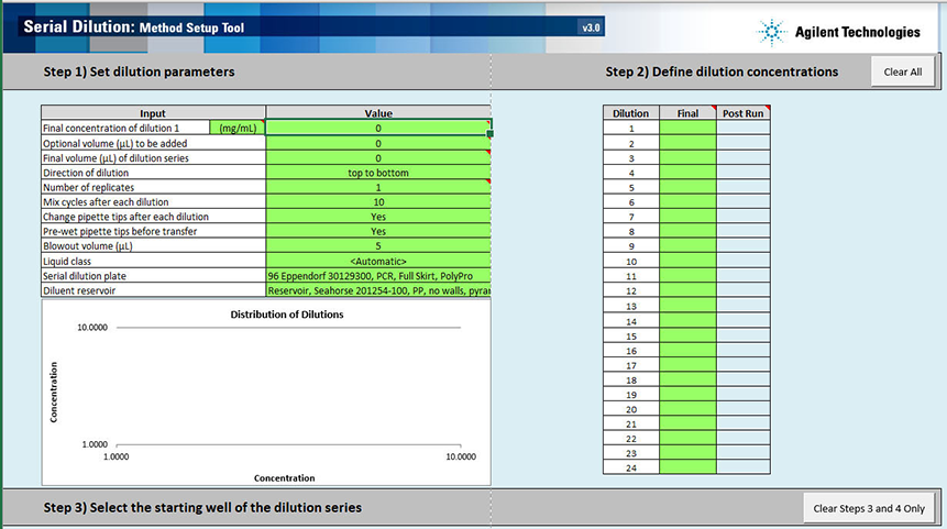
The Method Setup Tool is a Microsoft Excel-based tool that steps you through the process of creating and saving a method file that contains all the information required to run the Serial Dilution protocol on the AssayMAP Bravo Platform. This tool uses formulas to calculate volume requirements for the samples and diluent based on your input.
Note: When you select a method in the Serial Dilution utility, the form displays the corresponding labware selections and diluent preparation instructions.
Figure Serial Dilution Method Setup Tool
 |
Opening the Method Setup Tool
You can open the tool from the Utility Library or from the Serial Dilution form.
To open the Method Setup Tool:
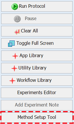
1 In the Utility Library, locate the Serial Dilution banner.
 |
2 Click one of the following buttons:
• Method Setup Tool. Microsoft Excel starts and displays the Method Setup Tool.
• Utility. The Serial Dilution utility opens.
In the navigation pane, click Method Setup Tool. Microsoft Excel starts and displays the Method Setup Tool.
 |
Overview of steps in Method Setup Tool
The Method Setup Tool has 6 distinct steps. The following table provides an overview of the steps.
Table Overview of steps in Method Setup Tool
Step | Description | ||
|---|---|---|---|
1 | Set dilution parameters | Enter values for the following inputs: | Default value (Range) |
Final concentration of dilution 1 | 0 (>0) | ||
Optional volume (µL) to be added | 0 (0 to < Final volume of dilution series) | ||
Final volume (µL) of dilution series | 0 (5–500) | ||
Direction of dilution | top to bottom (top to bottom, bottom to top, left to right, right to left) | ||
Number of replicates | 1 (1–5) | ||
Mix cycles after each dilution | 10 (0–100) | ||
Change pipette tips after each dilution | Yes (No/Yes) | ||
Pre-wet pipette tips before transfer | Yes (No/Yes) | ||
Blowout volume (µL) | 5 (0–50) | ||
Liquid class | Automatic (preset or custom) | ||
Serial dilution plate | |||
Diluent reservoir | |||
2 | Define dilution concentrations | Enter the final target concentration for each serial dilution step. | |
3 | Select the starting well of the dilution series | Click Select Starting Well, and then click the cell in the Serial Dilution Plate map where the replicate 1 of dilution 1 will be located. The setup tool will display the plate layout based on the input provided in steps 1 and 2. | |
4 | Calculate the sample and diluent volumes | Click Calculate Volumes. The setup tool calculates the required volumes of sample and diluent based on the input provided in steps 1 to 3. | |
5 | Correct these errors | Resolve any errors that the setup tool highlights. | |
6 | Create the method file | Click Create Serial Dilution Method. The setup tool creates a comma-separated value (.csv) text file that you use to run the utility. After you save the method, the Method Setup Tool closes. When you select the method in the Serial Dilution utility, the form displays the corresponding labware selections and diluent preparation instructions. Follow the instructions that appear in the form to prepare the serial dilution and diluent plates. | |
Step 1) Set dilution parameters
Note: Only the cells highlighted in green are editable.
To set the dilution parameters:
1 To clear any data from the Serial Dilution Method Setup Tool, click Clear All (upper right corner).
2 Specify the following values in the green cells:
For additional details on these settings, see Assay development guidelines.
Input | Description |
|---|---|
Final concentration of dilution 1 | |
Concentration units | In the Input column, verify that the unit of measure for the sample concentration is correct. If necessary, type the correct units (default is mg/mL). This input is used to populate other sections of the form. This value has no impact on the subsequent data or volume calculations. |
Concentration value | In the Value column, type the final concentration of the most concentrated level in the serial dilution series (e.g., Dilution 1 in Step 2). |
Optional volume (µL) to be added | The volume to be added manually or using the Reagent Transfer utility after the Serial Dilution run, for example, an internal standard. The set up tool uses this value to reduce the volume of the serial dilution to the final volume minus the optional volume to be added. The set up tool also uses this value to increase the concentration of each serial dilution step (see Post Run cells in Step 2) so that when the optional volume is added, the final serial dilution volumes and concentrations match the desired final serial dilution series volumes and concentrations. For example, if the Final volume = 50 µL and Optional volume to add later = 10 µL, the Serial Dilution steps will have a volume of 40 µL after the run, at which point the optional 10 µL will be added for a total volume of 50 µL. Default: 0 (µL) Range: 0–50 (µL) |
Final volume (µL) of dilution series | The final volume of each step in the dilution series. This includes the Optional volume (µL) to be added. Note: The practical range is approximately 20–500 µL, depending on the number and concentration of the dilution steps. The high end of the range is limited by well capacities and the high volume transfers required during the early steps of the dilution series compared to the final volume of the dilution steps. The low end of the range is limited by the requirement that the transfers be 5 µL or greater to ensure high precision and accuracy. Large-volume dilution series require more mix cycles (up to 100 for the largest volume serial dilutions) because of the limited volume that can be used for each mix cycle. The results for large volume dilution series may not be as accurate as smaller volume dilution series. Default: 0 (µL) Range: 5–500 (µL) |
Direction of dilution | The direction in which the dilution series should progress. The dilution series follows a serpentine pattern. See the example in Step 3) Select the starting well of the dilution series. Default: top to bottom Options: top to bottom, bottom to top, left to right, right to left |
Number of replicates | The number of replicates of each dilution step in the dilution series. Note: This cell turns yellow if you select 5 replicates. The yellow cautions you that the serial dilution may not fit on the serial dilution plate, depending on the number of steps in the dilution series. The maximum number of dilution steps with 5 replicates is as follows: • 16 for top-to-bottom or bottom-to-top dilution series • 12 for left-to-right or right-to-left dilution series The Number of replicates value determines the total number of wells that will be prepared for each step in the dilution series. For example, if the number of replicates is set to 2, then on run completion, there will be two wells containing each concentration in the series. Default: 1 Range: 1–5 |
Mix cycles after each dilution | The number of aspirate-and-dispense cycles used to mix the contents of the wells in the serial dilution plate. Default: 10 Range: 0–100 |
Change pipette tips after each dilution | The option to change pipette tips before transferring the sample for each dilution step. Default: Yes Options: Yes, No |
Pre-wet pipette tips before transfer | The option to wet the pipette tips with the sample before aspirating the sample. Note: Prewetting the pipette tips is a common pipetting technique that can increase accuracy in certain situations. Default: Yes Options: Yes, No |
Blowout volume (µL) | The volume of air to be drawn into the pipette tips before aspirating the sample. After dispensing the transferred sample, the volume of air remaining in the pipette tips is dispensed (blown out) while the tips are still in the wells. The blowout is followed by a tip touch on the east and west sides of the well. If the Blowout volume is set to 0, no blowout or tip touches will occur. Default: 5 (µL) Range: 0–50 (µL) |
Liquid class | The pipetting parameters (for example, aspiration and dispense speed). The liquid class selection strongly influences the pipetting precision and accuracy. This choice only controls the aspiration and dispense of the samples and diluent. The mixing speed of the dilutions is fixed at 300 µL/sec. Options: • <Automatic> (default). Automatically assigns one of the following liquid classes, based on the volume being transferred. 0–20 µL (AM_250uLTipsLowVol) > 20 µL (AM_250uLTipsHighVol) These are good general-purpose liquid classes for most reagents that are used with the AssayMAP system. • Slow Flow (5 µL/sec). A slower flow rate is better for viscous solutions. • Fast Flow (100 µL/sec). A faster flow rate may improve performance for high organic solutions. If these flow rates do not provide the desired performance, you may enter a custom liquid class. To create a custom liquid class, you use the VWorks Liquid Library Editor. For details on how to open the VWorks Liquid Library Editor, see To create a custom liquid class:. To enter a custom liquid class: In the Liquid Class box, type the liquid class name exactly as it appears in the VWorks Liquid Library Editor. Note: The estimated run time (Status box area) may not be accurate for methods that use a custom liquid class. |
Serial dilution plate | The labware that you are placing on the plate riser at deck location 6. For options, see Labware. For the capacity limits and the volume overage recommended for each labware, see the Labware Reference Guide in the Literature Library page of the workbench. Note: The intermediate volumes required to generate the serial dilution will be larger than the final volume of the serial dilution. If you have chosen a plate type whose capacity is lower than required, you will be alerted in steps 4 and 5. |
Diluent reservoir | The labware that you are placing on the plate riser at deck location 2. For options, see Labware. For the capacity limits and the volume overage recommended for each labware, see the Labware Reference Guide in the Literature Library page of the workbench. Be sure to choose a diluent reservoir that can hold the volume required for the serial dilution. The volume of diluent and the location where it should be placed will be given in step 7 of the Method Setup Tool. The plate type chosen must have enough well capacity to hold the dilution indicated in step 7 plus the required well overage. For volume guidelines, see Preparing the diluent and samples. Note: If the selected labware cannot hold the volume of diluent required for the serial dilution, an error message will appear in steps 4 and 5. |
Pipetting accuracy and liquid classes
Pipetting accuracy and precision can be greatly affected by liquid properties, such as viscosity and surface tension. If unacceptable accuracy and precision results are observed, you may modify these liquid classes to achieve acceptable results. Use the following procedure to modify or create a liquid class.
To create a custom liquid class:
1 In the Serial Dilution form, click Toggle Full Screen to change the display of the form so that the VWorks menubar and toolbar are visible, as the following figure shows.
Figure VWorks Tools menu and form displayed with full screen off
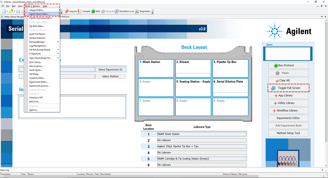 |
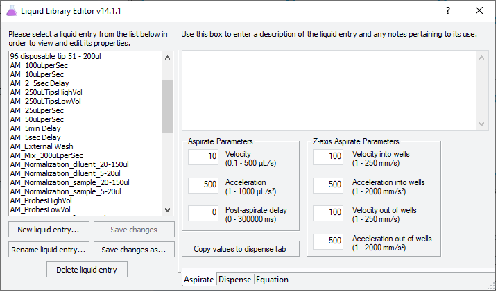
2 Click Tools > Liquid Library Editor. The Liquid Library Editor opens.
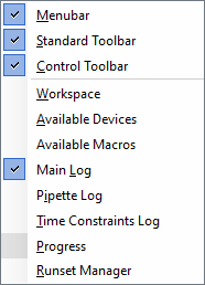
If the menubar is not visible in the window, right-click the window and select Menubar in the shortcut menu that appears.
 |
3 For instructions on how to use the Liquid Library Editor, see the section on specifying pipette speed and accuracy in the VWorks Automation Control Setup Guide.
Figure VWorks Liquid Library Editor window
 |
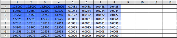
Step 2) Define dilution concentrations
To define the concentration of the serial dilution steps:
In the green boxes in the Final column, enter the desired concentration of each serial dilution step.
The method setup tool automatically enters the dilution concentration for dilution 1 when you enter the Final concentration of dilution 1 (Step 1) Set dilution parameters). You enter all the other concentrations in the dilution series directly in each cell or by entering a formula in the cell. You can use the Excel fill series function with formulas to quickly generate a serial dilution.
You can generate serial dilutions with 2 to 24 steps. You can also generate blanks by putting zero as a dilution concentration.
Note: If you enter zero as a concentration, an error message appears and says Negative or zero values cannot be plotted correctly on log charts. Only positive values can be interpreted on a logarithmic scale. To continue and use the zero, click OK. The graph will not include the zero volume but the method will work.
The Post Run column contains non-editable cells that show the concentration of the serial dilution series after the run is complete.
• If step 1 Optional volume to be added is >0, the Post Run column will show the concentration of the serial dilution steps after the serial dilution utility is run but before the optional volume is added. The concentrations entered in the Final column represent the concentration of the serial dilution after adding the optional volume.
• If step 1 Optional volume to be added is 0, the concentrations entered in the Final column will be the same as the those in the Post Run column.
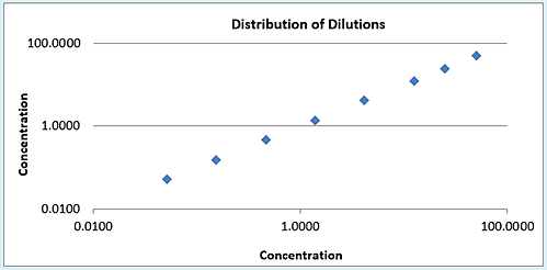
As you define the concentrations, the graph displays the corresponding log-log plot of the dilution series concentrations. You can use the graph to verify that your dilution formula will yield the expected results. The graph can help you visualize the distribution curve and identify gaps between dilution steps.
 |
Step 3) Select the starting well of the dilution series
To define the layout of the serial dilution plate:
1 Click Select Starting Well (figure, item 1) and then click the corresponding cell in the Serial Dilution Plate map where the replicate 1 of dilution 1 will be located (figure, item 2).
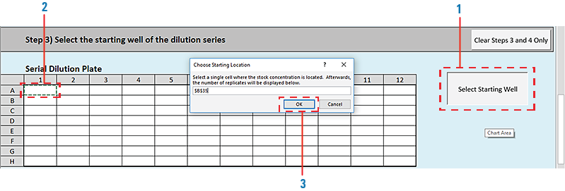 |
2 When the Choose Starting Location dialog box opens, displaying a formula, click OK (figure, item 3).
The layout for the dilution series appears in the Serial Dilution Plate map, displaying the selected number of replicates in the specified layout (row or column).
Figure Example of a left-to-right layout by row for a dilution series with 4 replicates
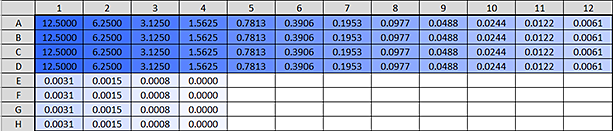 |
Figure Example of a top-to-bottom layout by column for a dilution series with 4 replicates
 |
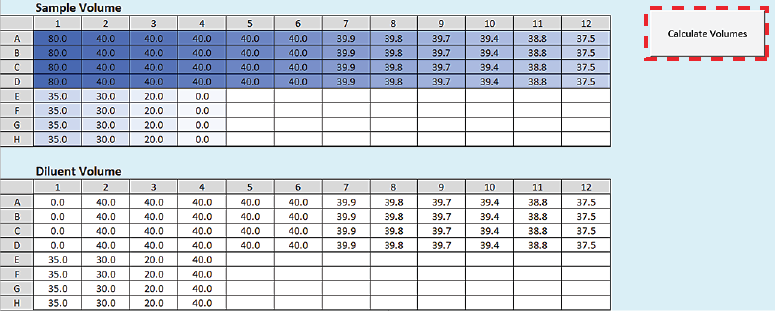
Step 4) Calculate the sample and diluent volumes
To calculate the sample and diluent volumes:
Click Calculate Volumes. The tool uses the information provided in the previous steps to calculate the sample and diluent volumes that will be transferred into each well to achieve the specified serial dilution series.
The calculated volumes (µL) appear in the following areas:
• Sample Volume plate map
• Diluent Volume plate map
 |
Step 5) Correct these errors
Although you may enter values that are not possible or practical given the selected labware or specified concentrations and volumes, the setup tool will flag such values as errors. You must resolve any errors before you can proceed to the next step in the setup tool.
Step 6) Create the method file
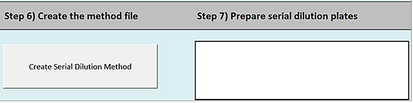 |
To create the Serial Dilution method file:
1 Click Create Serial Dilution Method.
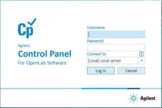
2 In the login window, type your VWorks user name and password, and click Log In.
 |
3 In the Save File dialog box, specify the file name and the storage location, and then click Save.
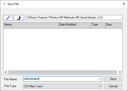 |
• VWorks Plus default storage location:
… /VWorks Projects/VWorks/AM Methods/AM Serial Dilution v3.0
… /VWorks Projects/VWorks/AM Methods/AM Serial Dilution v3.0
• VWorks Standard default storage location:
C:\OLSS Projects\VWorks Projects\VWorks\AM Methods\AM Serial Dilution v3.0
C:\OLSS Projects\VWorks Projects\VWorks\AM Methods\AM Serial Dilution v3.0
Note: The method file is stored as a record of interest (ROI) in an archive (.csv.roiZip). VWorks cannot load files (.roiZip extension) that have been modified or renamed outside of the Protein Sample Prep Workbench or VWorks software.
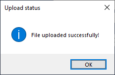
4 Click OK when the uploaded successfully message appears. The Method Setup Tool closes.
 |
Next steps:
If you want to view the method in Microsoft Excel, see Exporting and importing AssayMAP methods
If you are ready to prepare the serial dilution plates, see Preparing the diluent and samples.