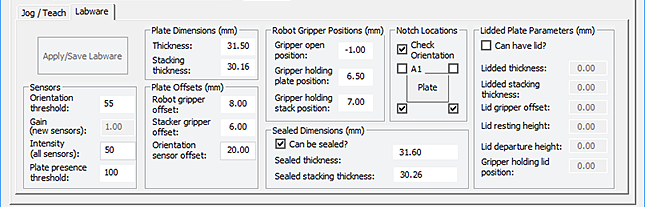
BenchCel Diagnostics - Labware tab
You can use the Labware tab to perform the following procedures:
The settings in the Labware tab are also available in the Labware Editor.
 |
Commands
Command | Description |
|---|---|
Apply/Save Labware | Saves the updated settings in the Labware tab. |
Plate Dimensions area
Parameters | Description |
|---|---|
Thickness | The distance (mm) from the bottom surface of the plate to the top surface of the plate. For a tip box, this is the distance from the bottom surface of the tip box to the top of the tips. To increase the number of contact points, measure the distance at the corner of the plate or tip box (using calipers). This method is especially useful if the plate has a lip at the top which could cause the caliper to angle inward, producing inaccurate measurements. 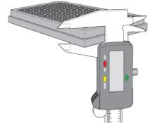 |
Stacking thickness | The thickness (mm) of two stacked plates minus the thickness of one plate. For example: Thickness of two stacked plates (x) = 23.14 mm Thickness of one plate = 14.14 mm Stacking thickness: 23.14 mm - 14.14 mm = 9.00 mm 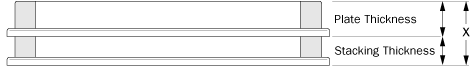 |
Sensors area
Parameters | Description |
|---|---|
Orientation threshold | The value that determines the presence of a microplate notch. A notch is present if the value is below this value. If the sensor value is above this threshold, no notch is reported. To check the sensors and for adjustment guidelines, see Setting sensor thresholds. Note: The setting is also available in the Jog/Teach tab. |
Plate presence threshold | The value that determines if a microplate is detected. Any value equal to or greater than the threshold means a microplate is present. A lesser value means there is no microplate. Note: The setting is also available in the Jog/Teach tab. |
Intensity (all sensors) | The intensity of the emitting sensor light. The value is a percent of the maximum intensity. Default: 50%. Some microplates are more reflective than others. Increase the intensity if microplate sensor readings are too low (not significantly higher than the corresponding threshold value) when either a microplate is present, or a notch is absent. Note: This setting applies to the plate-presence sensor, orientation sensor, and the rack-presence sensor. Changing this setting affects the sensor readings of the four orientation sensors. Always adjust the intensity and threshold values together. To check the sensors and for adjustment guidelines, see Setting sensor thresholds. |
Plate Offsets (mm) area
Parameters | Description |
|---|---|
Robot gripper offset | The distance (mm) from the bottom of a microplate to where the robot grippers will hold the microplate. |
Stacker gripper offset | The distance (mm) from the bottom of a microplate to where the stacker grippers will hold the microplate. |
Orientation sensor offset | The distance (mm) from the bottom of a microplate to where the orientation sensors will check for notches. See the procedure in Determining the optimum Orientation sensor offset. |
Robot Gripper Positions (mm) area
Parameters | Description |
|---|---|
Gripper open position | The distance (mm) the grippers move from the home position as the robot releases a microplate. A larger value moves the grippers closer together. A smaller value opens the grippers wider. |
Gripper holding plate position | The distance (mm) that the grippers move inward from their home position when holding a microplate that is not in a stack. A larger value moves the grippers closer together and holds the microplate tighter. A smaller value opens the grippers wider. Note: How tightly the robot grippers should hold a microplate depends on the microplate material and design. You might want to run some tests to optimize the parameter. |
Gripper holding stack position | The distance (mm) the grippers move inward from the home position when holding a microplate that is in a stack. A larger value moves the grippers closer together and holds the microplate tighter. A smaller value opens the grippers wider. Note: Because the weight of the entire stack will be on the robot grippers, you should use a value greater than the Gripper holding plate parameter. |
Notch Locations (mm) area
Options | Description |
|---|---|
Check orientation | Turns on or turns off the plate-orientation sensors. Select the check box to turn on the sensors. Clear the check box to turn off the sensors. |
Plate check boxes A1 | Indicates that the plate A1 corner has a notch. Clear the check box if the A1 corner does not have a notch. |
Upper right corner | Indicates that the plate upper right corner has a notch. Clear the check box if the upper right corner does not have a notch. |
Lower left corner | Indicates that the plate lower left corner has a notch. Clear the check box if the lower left corner does not have a notch. |
Lower right corner | Indicates that the plate lower right corner has a notch. Clear the check box if the lower right corner does not have a notch. |
Lidded Plate Parameters (mm) area
Parameters | Description |
|---|---|
Can have lid? | The option to include a microplate lid. If you select this option and plan to process lidded microplates, make sure you select the Plates have lids check box under the graphical display area. |
Lidded thickness | The thickness (mm) of the plate with a lid in place. Available only if Can have lid? is selected. |
Lidded stacking thickness | The stacking thickness (mm) of the plate with the lid in place. Available only if Can have lid? is selected. |
Lid gripper offset | The height (mm) above the lid resting height at which to grip the lid. (Shown as b below.) 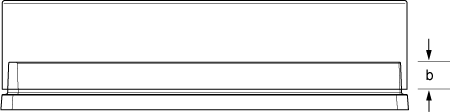 |
Lid resting height | The height (mm) above the bottom of the plate at which the bottom of a plate lid rests. (Shown as a below.) 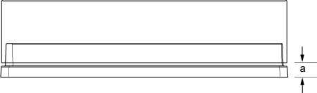 |
Lid departure height | The height (mm) above the bottom of the plate to which the lid is lifted. 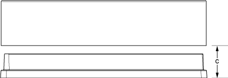 |
Gripper holding lid position | The distance (mm) the grippers move inward from home position when holding a microplate lid. Increasing the value moves the grippers closer together and holds the lid tighter. Decreasing the value opens the grippers wider. In general, type a value that is less than the Gripper holding plate position to open the grippers slightly. Holding the lid too tightly might cause the microplate to be lifted with the lid. |