Determining the optimum Orientation sensor offset
About this topic
Before starting this procedure, make sure you are familiar with the workflow in Overview for setting sensor thresholds.
Procedure
To determine the optimum Orientation sensor offset:
1 On the Controls page at Stacker 1, click Downstack from Stacker.
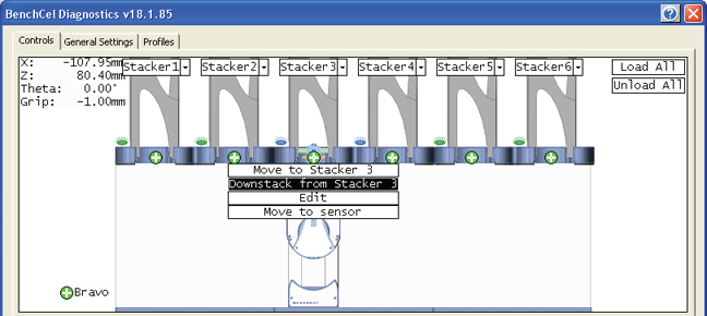 |
2 On the Labware tab, verify that the Orientation sensor offset box contains the initial offset value you want to use for the selected labware.
If you have not already done so, follow these steps to determine the initial value for the Orientation sensor offset:
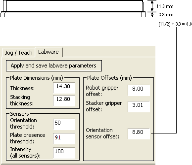
a Determine the midpoint height (mm) of the microplate. To do this, measure from the top of the microplate skirt to the top of the microplate and divide by 2.
b Measure the height (mm) of the microplate skirt.
c Add the values from step a and step b.
Figure Example of initial Orientation sensor offset calculation
 |
3 On the Controls page at Stacker 1, click Move to sensor. The robot moves the first microplate into the line of notch sensors.
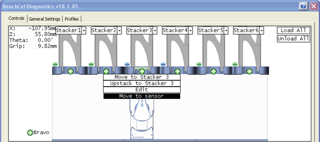 |
4 On the Jog/Teach tab, make sure the Notch Sensors readings are appropriate. The notches should have much lower readings than the corners. In addition, the difference between the notch readings and corner readings should be at a maximum.
In the following example, the Notch Sensors values indicate that the microplate has two notches (3 and 7) and two corners (76 and 63).
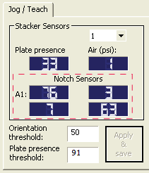 |
5 To find the maximum difference between the notch readings and corner readings:
a On the Controls page, locate the initial z-axis position (Zinitial) in the upper left corner. Record the value.
b Use the controls on the Jog/Teach tab to jog the robot up or down, and then check the Notch Sensors readings. You can repeat this step until you find the maximum difference between the notch readings and the corner readings.
c Record the adjusted z-axis position (Zadjusted).
6 Calculate the jog distance:
Jog distance = Zinitial – Zadjusted
In the following example, the jog distance is –5.00 mm.
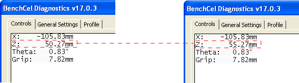 |
Zinitial | 50.27 mm |
Zadjusted | 55.27 mm |
Jog distance | –5.00 mm |
7 Calculate the adjusted Orientation sensor offset using the following formula:
Adjusted Orientation sensor offset = Initial Orientation sensor offset + Jog distance
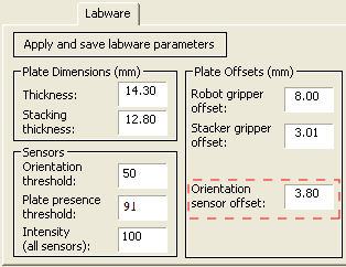
In the following example, the adjusted orientation sensor offset is 3.80 mm.
Initial Orientation sensor offset | 8.80 mm |
Jog distance | –5.00 mm |
Adjusted Orientation sensor offset | 3.80 mm |
8 On the Labware tab, type the adjusted Orientation sensor offset.
 |
9 On the Control page at the next stacker, click Downstack from Stacker, and then click Move to sensor. Check the Notch Sensors readings on the Jog/Teach tab. The notches should have much lower readings than the corners. In addition, the difference between the notch readings and corner readings should be at a maximum.
10 Repeat step 9 for the remaining stackers.
Related information
For information about… | See… |
|---|---|
Workflow for setting sensor thresholds | |
Worksheet for sensor thresholds | |
Previous step in this workflow | |
Next step in this workflow |