Installing a Heating Shaking Station
About this topic
This topic describes how to install the Heating Shaking Station and presents the workflow for configuring the accessory in the software.
Description
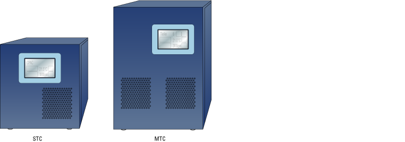
The Heating Shaking Station provides fluid mixing and heating for microplates. The Heating Shaking Station uses a short adapter pad to attach to the Bravo deck. The station uses the Inheco Single TEC Control (STC) or Multi TEC Control (MTC) to connect to the computer and power source.
Figure Heating Shaking Station and adapter pad
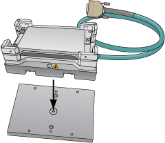 |
Figure STC and MTC Controllers
 |
Before you start
The Heating Shaking Station may be installed at any deck location using the short adapter pad instead of a platepad.
• Heating Shaking Station, including adapter pad, M6 x 12 flathead screw (to attach the adapter pad), and two M3 x 18 socket-head cap-screws
• 2.5-mm and M5 hex wrenches
• Inheco STC or MTC Controller with the corresponding PCA installed for the Heating Shaking Station, power and communication cables, and Inheco user documentation
Use the following workflow.
Step | For this task... | See... |
|---|---|---|
1 | Set up the Inheco MTC or STC Controller. For guidance, contact Agilent Technical Support. | Manufacturer documentation |
2 | Install the Heating Shaking Station on the Bravo deck. | |
3 | Set up the station in the software: a Configure the station in the Bravo profile. b Test the station functioning. c Set the teachpoint. |
Installing the Heating Shaking Station
To install the Heating Shaking Station:
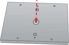
1 Remove the M6 screw in the center of the platepad. Remove the platepad.
2 Position the adapter pad in the predetermined deck location aligning the dowel pins in the corresponding holes on the deck.
Make sure the adapter pad sits level on the deck.
3 Insert the M6‑x‑12‑mm flathead screw into the center of the adapter pad and tighten the screw.
 |
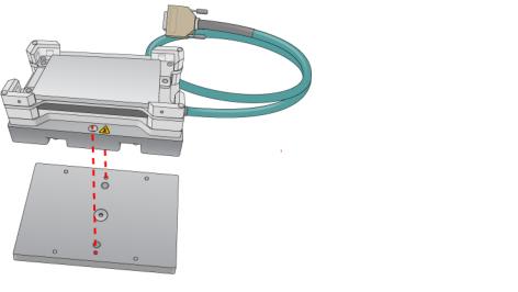
4 Place the Heating Shaking Station on top of the adapter pad.
Ensure that the station sits level on the adapter pad and the safety label  faces the front of the workspace.
faces the front of the workspace.5 Insert the two M3‑x‑18‑mm socket-head cap screws into the holes at the front and back end of the adapter pad and use the 2.5‑mm hex wrench to tighten the screws.
 |
6 Determine if the pairs of alignment tabs (figure, item 1) in each corner of the plate nest require adjustment as follows:
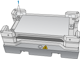 |
a Position a labware in the plate nest, ensuring that it is fully seated.
b Make sure that the labware fits in the nest so that it is not too loose or too tight. To test the fit, lift the labware and re-seat it several times.
c If necessary, use a flathead driver to adjust the setscrews so that the tabs are recessed or extended, as needed.
7 Connect the cables:
a Connect the cable from the Heating Shaking Station to the Inheco STC or MTC Controller.
Note: The accessory cable is color-coded to match the card installed in the STC or MTC.
b Connect the STC or MTC Controller power and communication cables. See the Inheco user documentation for details on how to connect the STC or MTC.
c Press the STC or MTC Controller power switch to the on (|) position.
Figure MTC Controller (front and back views)
 |
After installing the accessory, you configure it in the Bravo profile, establish communication, and set the teachpoint for the location.
Related information
For information about… | See… |
|---|---|
Configuring and teaching the Heating Shaking Station | |
Using the accessory in a protocol | VWorks Automation Control User Guide |