Setting up thermal and shaking stations (Inheco controller)
About this topic
This topic describes how to configure the Bravo thermal and thermal shaking accessories that are controlled by the Inheco Single TEC Controller (STC) or Multi TEC Controller (MTC). The Inheco STC and MTC controlled accessories include the following:
Accessory name | Corresponding Inheco name |
|---|---|
Peltier Thermal Station | CPAC Ultraflat |
Heating Shaking Station | Teleshake 95 |
The STC can control a single Inheco device, and the MTC can control multiple Inheco devices. For a detailed description of the Inheco STC or MTC, see the Inheco STC or MTC user documentation.
Figure Inheco STC and MTC Controllers
 |
Configuring an Inheco station
To configure an Inheco station in Bravo Diagnostics:
1 In Bravo Diagnostics, click the Profiles tab, and verify that the correct profile is initialized.
2 Click the Configuration tab.
3 In the Location is configured as list, select Accessory. The Accessories Wizard opens.
4 In the Accessories Wizard, select the Location of the installed accessory. In the Choose Accessory page, select Heating Shaking Station.
5 Enter the following values in the accessory parameters page.
a In the MTCSTC Id box, select the ID number of this device. The ID number identifies the specific device for the VWorks software.
Note: The ID number is set using a DIP switch control on the rear panel of the Inheco STC or MTC Control. See the Inheco user documentation for a description of how to set the ID for each slot on the STC or MTC device.
b Select the MTCSTC Type, either STC or MTC.
c In the Slot Id box, select the slot number on the Inheco STC or MTC rear panel where the accessory’s cable is connected.
Note: The STC has only one slot.
6 Click Finish.
7 When the configuration message appears, click Yes to initialize the accessory and move the teachpoint to a safe height.
8 In the Profiles tab, click Update this profile.
9 VWorks Plus only. If an audit trail is being logged, the Audit Comment dialog box opens. Select or type the audit comment, and then click OK.
10 Edit the location’s teachpoint for the accessory. See Teaching a thermal or thermal shaking station.
Testing a thermal or thermal shaking station
The following warning symbol appears on the thermal stations, warning you of the potential burn hazard.
 |
To test the station:
1 Ensure that the connected STC or MTC power switch is set to the On position.
2 In Diagnostics, ensure the correct profile is initialized, and then click the Configuration tab.
3 In the Accessory Configuration area, select the Heating Shaking Station, and then click Diagnose accessory.
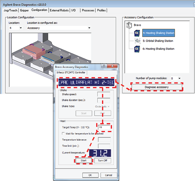 |
4 In the Bravo Accessory Diagnostics dialog box, verify that the correct device appears in the display at the top.
Note: The software obtains the device name from the STC or MTC, and then the Inheco name of the device appears in the display of the dialog box, for example, CPAC Ultraflat or Teleshake 95.
5 Shaking accessories only. Set the parameters in the Shake area:
a In the Shake speed box, type the shaking speed.
b In the Shake duration box, type the time duration (seconds).
c In the Shake type box, select the type of stirring motion.
d Click Start to test the shake parameter settings. At the device, verify that the accessory operates correctly.
Click Stop to turn off the shaking feature.
6 Thermal accessories only. In the Heat area, set the parameters to test the temperature function:
a In the Target temp box, type the temperature (°C).
b To specify a time limit within which to reach the target temperature, select the Wait for temperature to be reached check box, and then set the following:
• In the Temperature tolerance box, type the ±°C.
• In the Time limit box, type a time limit (minutes).
c Click Start to test the Heat parameter settings. At the device, verify that the accessory operates correctly.
Click Turn Off to stop the heating or cooling.
7 Click OK to close the dialog box.
Teaching a thermal or thermal shaking station
The teaching procedure can vary depending on the combination of microplate, plate nest, and adapter. The procedures in this section are for the following configurations on a Bravo Platform with a disposable-tip head:
• Peltier Thermal Station with generic plate nest and adapter
• Heating Shaking Station
The microplate bottom surface configuration affects how it sits in the station’s plate nest. The following figure shows a skirted microplate in a Peltier Thermal Station that has a generic plate nest and adapter. In the figure, the well bottoms rest on the top of the adapter (1), and the skirt rests on the top of the plate nest’s lower surface (2).
Figure Skirted microplate sitting in Peltier Thermal Station with generic plate nest and adapter (cut-away side view)
 |
As the figure shows, the height difference between the adapter top (1) and the plate nest top (2) enables a skirted microplate to nest in the station. The well bottoms must sit directly on the adapter top to enable an efficient temperature transfer. However, the teachpoint must account for this height difference to ensure that the Bravo robot grips the microplate at the correct position and performs pipetting tasks at the correct height.
To set the teachpoint for a generic Peltier Thermal Station or Heating Shaking Station:
1 Place the microplate securely in the plate nest of the thermal station. Verify that the microplate sits in the plate nest so that the well bottoms are resting on the adapter and the skirt rests in the plate nest bottom surface. Remove the microplate.
2 Using calipers, measure the height difference between the adapter top (1) and the plate nest top (2) on all four sides of the plate nest interior. Make a note of the smallest number. Later in the procedure, you will add this value to the z-axis value for the teachpoint.
3 Place the teach plate in the plate nest.
Note: Alternatively, you can use a 384-well microplate instead of the teach plate to set the teachpoint xy coordinates. In this case, you set the xy coordinates based on the center of the A1 well quadrant, as the following figure shows.
 |
4 In Bravo Diagnostics, click the Profiles tab, and initialize the desired profile.
5 In Bravo Diagnostics, click the Processes tab, select a tip box, and perform a Tips On command. For details, see Performing a task using Bravo Diagnostics.
6 In Bravo Diagnostics, click the Jog/Teach tab, and set the initial teachpoint as follows:
a Select the deck location of the station from the Location list.
b Use the controls to jog the head so that the A1 pipette tip is directly over the crosshairs with paper-thin clearance. For details, see Setting the first teachpoint.
c Click Teach to set the teachpoint.
d In the Profiles tab, click Update this profile.
e VWorks Plus only. If an audit trail is being logged, the Audit Comment dialog box opens. Select or type the audit comment, and then click OK.
7 Adjust the teachpoint z-axis value for the teach plate height as follows:
a Jog the head up in the z‑axis so that you have enough room to remove the teach plate. Remove the teach plate.
b In the Jog/Teach tab, use the controls to jog the head down in the z‑axis until there is paper-thin clearance between the end of the tip and the top surface of the adapter.
Note: When the z-axis error message appears, you may click Ignore.
c Click Teach to set the teachpoint.
d In the Profiles tab, click Update this profile.
e VWorks Plus only. If an audit trail is being logged, the Audit Comment dialog box opens. Select or type the audit comment, and then click OK.
8 In Bravo Diagnostics, click the Processes tab, select the empty tip box, and perform a Tips Off command. For details, see Performing a task using Bravo Diagnostics.
9 Adjust the teachpoint z-axis value for the height difference between the adapter and the plate nest as follows:
a In the Jog/Teach tab, select the deck location of the station, and click Move.
c Click Teach to set the teachpoint.
d In the Profiles tab, click Update this profile.
e VWorks Plus only. If an audit trail is being logged, the Audit Comment dialog box opens. Select or type the audit comment, and then click OK.
To verify the teachpoint by performing a pick and place:
1 In Diagnostics, click the Gripper tab.
2 Select the Labware from the list.
3 In the Location A list, select a deck location.
4 In the Location B list, select the thermal station location.
5 Place a test microplate on deck location A, and then click the following:
• Pick A -> B to pick up the microplate from deck location A and place it on deck location B.
• Pick B -> A to pick up the microplate from deck location B and place it on deck location A.
6 Make sure that the gripper holds the microplate securely and keeps it level while moving the microplate from location to location. Ensure that the gripper places, but does not drop the microplate at the destination location.
Related information
For information about… | See… |
|---|---|
Heating Shaking Station | |
Peltier Thermal Station | |
Using the accessory in a protocol | VWorks Automation Control User Guide |