Setting teachpoints
About this topic
This topic explains how to set teachpoints.
If you are teaching the AssayMAP Bravo Platform, see the AssayMAP Bravo Platform Installation Guide.
You must set or edit teachpoints anytime the following occurs:
• You are using a new liquid-handling head for the first time
• The existing teachpoint files are lost or damaged
• You first set up your Bravo Platform
• You change the teaching tip type in the profile
• You add an accessory
Teachpoint defined
A teachpoint is a set of axial coordinates that define a location to which the liquid-handling head moves. Each of the nine locations on the Bravo deck has a default teachpoint that can be edited in Bravo Diagnostics. The default teachpoints are set so that well A1 is at the back left corner of each deck location.
Before you start
Make sure you do the following:
• Remove all labware from the Bravo deck locations.
• Verify that the correct liquid-handling head is installed and the corresponding profile is initialized.
If you are teaching a pin tool, see Workflow for non-tip-box locations.
Workflow for non-tip-box locations
Step | For this task... | See... |
|---|---|---|
1 | Set the first teachpoint. Use a deck location that is easy to access, for example, deck location 1, 4, or 7. | |
2 | Set teachpoints for the remaining locations by doing one of the following: • Automatically set the remaining teachpoints based on the first teachpoint. | |
• For more precise teachpoints (384- or 1536-well plates), repeat step 1 for each deck location. | ||
3 | Verify each teachpoint. | |
4 | Edit the teachpoint, as required, for any accessory locations, such as the Weigh Station or an Orbital Shaking Station. | The procedure can vary depending on the accessory. For details, see Bravo accessories overview. |
Workflow for a tip box location
Pressing pipette tips on the liquid-handling head requires a high degree of precision in the positioning of the head relative to the tip box, especially for 384-well tip boxes. Use the following workflow for deck locations where you plan to place either a tip box.
Step | For this task... | See... |
|---|---|---|
1 | Determine the platepad requirements for the tip box location: | |
• Standard Bravo Platform – ST tip box. Use an Alignment Station instead of a standard platepad at the deck locations where you perform tip box operations. The Alignment Station helps provide greater tip-loading precision. | ||
– LT tip box. If using a 250‑µL tip box, you can use a standard platepad or an Alignment Station. Note: If using a 200‑µL tip box, use a standard platepad and an LT insert for tip loading. | – | |
– Nested tip box. Install and configure the Nested Rack Insert. | ||
• SRT Bravo Platform – ST tip box. Use an ST tip loading station. – 250-µL tip box. Install the 250‑µL platepad and configure the deck location. | ||
2 | Set the teachpoint for the location. | |
3 | ST tip box locations. Verify the labware definition for the tip box. | |
4 | Verify the teachpoint. If tip-box operations are not precise enough, repeat this step. |
Setting the first teachpoint
If you are using a:
• Disposable-tip head, place the teaching tip type that you specified in the profile on the A1 barrel or probe to set the teachpoint.
• Bravo 96AM Head, see the AssayMAP Bravo Platform Installation Guide.
• Pin tool, set the teachpoint according to the A1 needle.
To set the first teachpoint:
1 In Bravo Diagnostics, click the Profiles tab, and initialize the desired profile.
2 Disposable-tip heads. Place a pipette tip firmly on the head barrel that corresponds to the A1 well of the labware you are using.
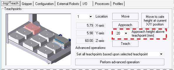
3 Click the Jog/Teach tab.
4 In the Location list, select the deck location. If you are setting up the first teachpoint, select location 1, 4, or 7.
Note: The teachpoint coordinates for the selected location are displayed under the Location list.
5 Set the Approach height above teachpoint to a safe distance, such as 20 mm, and then click Approach.
 |
6 Use the Jog Axes controls to move the liquid-handling head to the correct teachpoint as follows:
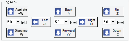 |
a Jog the head down (z-axis) until the A1 tip is approximately 2 mm above the platepad.
Reduce the increment value when the tip gets close to the deck.
b Jog the head in 0.05 mm increments in the x and y directions, until the tip is positioned directly above the crosshair mark on the platepad.
c To achieve paper-thin z-axis clearance, slide a sheet of paper between the tip and the platepad. Set the z-axis increment to 0.05 mm increments. Jog the head down until the paper is barely pinched, and then jog up by 0.05 mm.
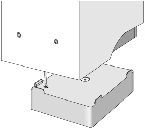
7 When the tip is in the correct position (directly over the crosshair mark with paper-thin clearance), click Teach.
Verify the information in the message box before you click OK.
Figure Pipette tip A1 position over the platepad crosshair mark
 |
8 To save the teachpoint, click the Profiles tab and click Update this profile.
VWorks Plus only. If an audit trail is being logged, the Audit Comment dialog box opens. Select or type the audit comment, and then click OK.
Setting other teachpoints based on one teachpoint
After setting the first teachpoint, you can have the VWorks software calculate the other eight teachpoints based on the selected teachpoint. Typically, this is done upon initial setup of a new liquid-handling head.
To set the other eight teachpoints:
1 In the Jog/Teach tab, verify that the teachpoint you just taught (Setting the first teachpoint) is set in the Location list.
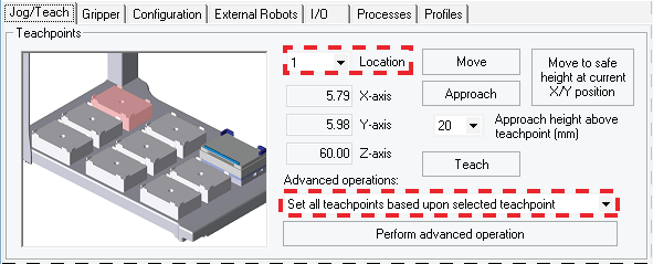 |
The teachpoint for the other locations will be set based on this one.
2 In the Advanced operations list, select Set all teachpoints based upon selected teachpoint.
3 Click Perform advanced operation.
The VWorks software calculates the teachpoints for the other eight locations, keeping the z-axis coordinate the same and changing the x and y coordinates according to their spacing.
4 Readjust the z-axis height for any positions that are taller than a standard platepad, such as the Orbital Shaking Station.
5 To save the teachpoints, click the Profiles tab and click Update this profile.
VWorks Plus only. If an audit trail is being logged, the Audit Comment dialog box opens. Select or type the audit comment, and then click OK.
Verifying teachpoints for disposable-tip heads
Verify the following:
• The labware definition for the tip box contains the correct column-wise and row-wise teachpoint-to-well values.
• The teachpoint is accurate for proper tips-on and tips-off operations.
To verify the tip box labware definition:
1 Open the Labware Editor.
2 In the Pipette/Well Definition tab, verify the following values for the tip box labware definition:
Large transfer (LT) tips | Small transfer (ST) tips |
|---|---|
Row-wise teachpoint to well (mm) = 0 | Row-wise teachpoint to well (mm) = 2.25 |
Column-wise teachpoint to well (mm) = 0 | Column-wise teachpoint to well (mm) = 2.25 |
To verify the teachpoint accuracy:
1 Open Bravo Diagnostics, and click the Jog/Teach tab.
2 Click Move to safe height at current X/Y position to move the head up so that you have enough room to remove the single pipette tip from the head barrel.
3 Place a tip box full of tips on the tip box location that you are verifying. Make sure the tip box is sitting level on the platepad.
4 Perform a tips-on operation as follows to ensure the tips are loaded properly:
a Click the Processes tab.
b In the Command to Execute list, select Tips On.
c Click Execute Command. The head presses down to install the tips, and then moves back up.
5 Remove the empty tip box from the deck location.
6 In the Jog/Teach tab, click Move. The head moves to the teachpoint you set in Setting the first teachpoint. You might notice that the A1 tip is not quite in the correct position.
7 Use the Jog Axes controls to move the head A1 tip to the correct position (directly over the crosshairs with paper-thin clearance).
8 When you are finished, click Teach. Verify the information in the message box before you click OK.
10 To save the changes, click the Profiles tab and click Update this profile.
VWorks Plus only. If an audit trail is being logged, the Audit Comment dialog box opens. Select or type the audit comment, and then click OK.
Verifying teachpoints for pin tools
After setting and saving teachpoints, you should verify each teachpoint.
To verify a teachpoint:
1 In the Jog/Teach tab, set the Location field to the location you want to check.
2 Click Approach.
3 Use the following table to decide your next step:
If the A1 needle is … | Then … |
|---|---|
Above the crosshairs at the approach height | a Click Move to move the A1 needle to the teachpoint. b Visually check the position. The tip of the needle should be directly over the crosshairs with a clearance of about the thickness of a sheet of paper. (If it is not, repeat Setting the first teachpoint.) |
Not above the crosshairs or appears to be closer to the deck than the approach height | There is a problem with the teachpoint. Repeat Setting the first teachpoint. |
4 Repeat the above steps for each teachpoint.
Related information
For information about… | See... |
|---|---|
The workflow this procedure belongs to | |
Creating and initializing a profile | |
Changing the liquid-handling head |