Installing and configuring the Peltier Thermal Station
About this topic
This topic describes how to install the Peltier Thermal Station and presents the workflow for configuring the accessory in the software.
Description
The Peltier Thermal Station uses Peltier technology to provide temperature control uniformly across a microplate. The station can be fitted with a variety of plate nests and adapters to provide efficient temperature control for different types of microplates.
This accessory requires the Bravo risers to raise the Bravo deck surface and accommodate the height of the accessory below the deck. To install Bravo risers, contact Agilent Technical Support.
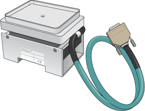
The following figure shows the Peltier Thermal Station fitted with the custom plate nest.
Figure Peltier Thermal Station with custom plate nest
 |
Before you start
Ensure you have the following:
• Bravo Platform with risers installed
The Peltier Thermal Station is too tall to sit at deck level and must be installed in a deck cutout at deck location 4 or 6, as the following figure shows.
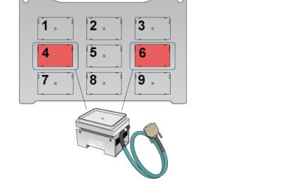 |
• Peltier Thermal Station assembly, including four M2.5 bolts and one M3 flathead cap screw
• Hex drivers
• Inheco STC or MTC Controller with PCA installed for Peltier Thermal Station, power and communication cables, and Inheco user documentation
Use the following workflow.
Step | For this task... | See... |
|---|---|---|
1 | Set up the Inheco MTC or STC Controller. For guidance, contact Agilent Technical Support. | Manufacturer documentation |
2 | Install the Peltier Thermal Station on the Bravo deck. | |
3 | Set up the station in the software: a Configure the station in the Bravo profile. b Test the station functioning. c Set the teachpoint. |
Installing the Peltier Thermal Station
To install the Peltier Thermal Station:
1 Uninstall the platepad, if applicable, from either deck location 4 or 6.
To uninstall a platepad, remove the M6 flathead screw from the center of the platepad. Remove the platepad from the deck.
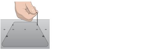
2 Remove the four M3 screws that attach the cutout cover to the deck.
Figure Cutout cover on the Bravo deck
 |
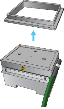
3 Uninstall the plastic interface from the top of the Peltier Thermal Station by removing the four screws located at the four corners.
Figure Plastic interface on the top of the Peltier Thermal Station
 |
 |
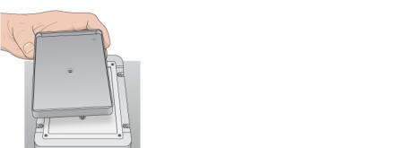
4 Refer to the following figure, and then place the Peltier Thermal Station assembly into the cutout hole as follows:
Figure Placing the Peltier Thermal Station into the deck hole
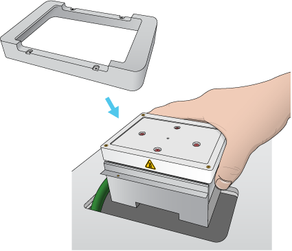 |
a Carefully slide the cable into the cutout hole first before you place the Peltier Thermal Station assembly into the cutout.
b Ensure that the safety label  faces the front of the Bravo deck.
faces the front of the Bravo deck.c Press and hold from the bottom to squeeze in the metal as you insert the Peltier Thermal Station assembly into the hole.
d Position the bracket around the outside edges of the top area of the assembly.
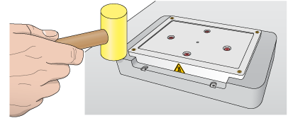
e If there is slight resistance when fitting the assembly into the cutout or when positioning the bracket, you may use a rubber mallet to tap the metallic base or bracket into place.
Figure Tapping the Peltier Thermal Station bracket in place
 |
f Ensure that the Peltier Thermal Station sits flush in the cutout and that the bracket is seated on the Bravo deck.
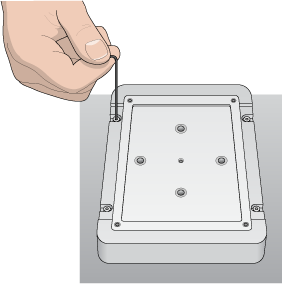
5 Install the four M2.5 bolts that secure the bracket to the deck.
Figure Securing the Peltier Thermal Station to the deck
 |
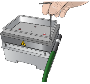
6 Install the custom plate nest on the plastic top of the Peltier Thermal Station as follows:
a Position the plate nest and ensure that it is fully seated.
b Install the M3 screw in the center of the plate nest to secure it to the Peltier Thermal Station.
Figure Installing the custom plate nest
 |
7 Connect the cables:
a Connect the cable from the Peltier Thermal Station to the Inheco STC or MTC Controller.
Note: The accessory cable is color-coded to match the card installed in the STC or MTC.
b Connect the STC or MTC Controller power and communication cables. See the Inheco user documentation for details on how to connect the STC or MTC.
c Press the STC or MTC Controller power switch to the on (|) position.
Figure MTC Controller (front and back views)
 |
After installing the accessory, you configure it in the Bravo profile, establish communication, and set the teachpoint for the location.
Related information
For information about… | See… |
|---|---|
Configuring the Peltier Thermal Station in the Bravo profile and setting the teachpoint | |
Using the accessory in a protocol | VWorks Automation Control User Guide |