Hardware overview
About this topic
This topic describes the Bravo Platform primary hardware components and the axes of motion.
Primary hardware components
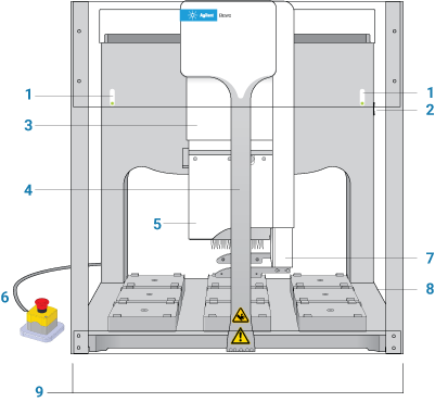
The following figure and table describe the primary Bravo hardware components.
Figure Bravo Platform components (front view)
 |
Item | Feature | Description |
|---|---|---|
1 | Indicator lights | The two light panels that display color-coded status of the Bravo Platform: •  (solid blue). The Bravo Platform is turned on and in standby mode. (solid blue). The Bravo Platform is turned on and in standby mode.•  (flashing green). The software is running a protocol on the Bravo Platform. (flashing green). The software is running a protocol on the Bravo Platform.•  (flashing orange). The software has initialized the Bravo Platform and Bravo Diagnostics is open. (flashing orange). The software has initialized the Bravo Platform and Bravo Diagnostics is open.•  (flashing red). The software has encountered an error while running a protocol or the interlock circuit is tripped. (flashing red). The software has encountered an error while running a protocol or the interlock circuit is tripped. |
2 | Power switch | The switch on the right side of the rear wall that turns on (I) and off (O) the Bravo Platform. |
3 | Head mount | The fixture that provides the mechanical connections and communication inferface for the liquid-handing head. The head mount attaches to an arm that extends from the Bravo rear wall of the tie bar. The head mount travels along the arm between the front and back of the deck (y-axis). The arm moves the head mount from side to side across the deck (x-axis). For details, see Axes of motion. You can move the head mount manually while the Bravo Platform is turned off. |
4 | Tie bar | The vertical bar at the front of the device that adds structural support to the Bravo head mount. The tie bar moves at high speed from side to side (x‑axis) across the front of the Bravo deck whenever the head moves to a deck location. |
5 | Liquid-handling head | The platform uses interchangeable Bravo-compatible heads, including disposable-tip heads, the Bravo 96AM Head for AssayMAP cartridges, and pin tools. The following figure shows an example of a disposable-tip head. Figure Series III disposable-tip head 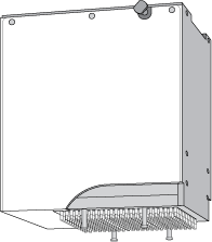 |
6 | Emergency-stop pendant | The pendant that contains the red emergency-stop button. To stop in an emergency, press the red button. All Bravo motion stops. 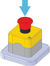 |
7 | Gripper | An optional gripper that extends from the head mount to below the pipette head tips. The gripper picks and places labware on the deck. |
8 | Deck | The area that is accessible by the liquid-handling head. The deck supports nine deck locations that are numbered 1–3 (back row), 4–6 (middle row), and 7–9 (front row). Each deck location holds a platepad or an accessory. The Bravo Platform ships with nine platepads, one on each location. You may remove a deck-mounted platepad to install certain accessories. Figure Nine deck locations (top view) 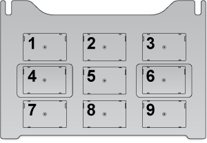 |
9 | Light curtain and front and side shields | The safety equipment that reduces the risk of injury to users from Bravo moving parts. If an object disrupts the light curtain, the motion of the Bravo head stops. For details on the Bravo safety equipment, see the G5562A, G5563A Bravo Platform Safety and Installation Guide. |
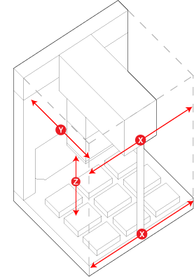
Axes of motion
The Bravo Platform has components that move in the x-, y-, and z-axes, as the following figure shows.
Figure Bravo Platform primary axes of motion
 |
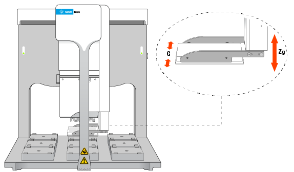
If the Bravo Platform is fitted with a gripper, the gripper moves with the Bravo head. In addition, the gripper has the following axes of motion:
• G‑axis. The opening and closing distance of the gripper fingers, which enable the gripper to grip and release labware.
• Zg‑axis. The vertical distance the gripper arm moves, which enables the gripper to extend beyond the pipette head.
Figure Bravo gripper assembly axes of motion
 |
The motion of the displacement of the pipettor inside a liquid-handling head is referred to as the w‑axis (not shown).
Related information
For information about... | See... |
|---|---|
Pipette head | |
Connection panel | |
Accessories | |
Laboratory requirements | G5562A, G5563A Bravo Platform Safety and Installation Guide |
AssayMAP Bravo Platform | AssayMAP Bravo Platform Getting Started Guide |