AM Dispense (Agilent Bravo)
Description
The AM Dispense (Agilent Bravo) ( ) task is designed for dispensing fluids through AssayMAP Bravo cartridges that are mounted on the Bravo 96AM Head.
Task is available for... | Task is available in... |
|---|---|
Bravo Platform with Bravo 96AM Head | Main Protocol, Bravo Subprocess |
The AM Dispense (Bravo) task has the same task parameters as the Dispense (Bravo) task, except for the following parameters:
• Override dispense flow rate from liquid class
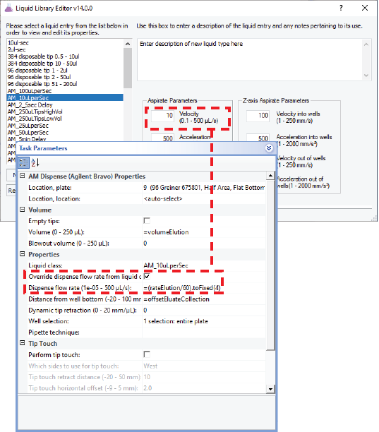
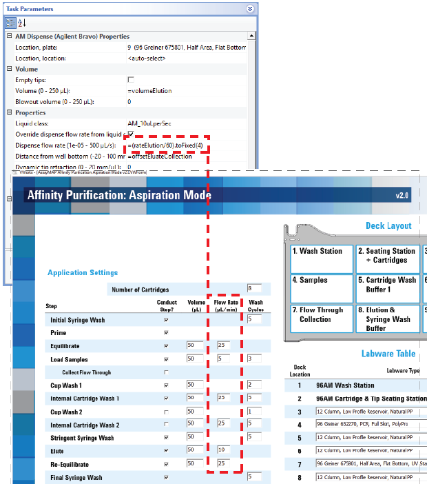
Precise flow-rate control is critical for the performance of the AssayMAP Bravo cartridges. The option to override the dispense flow rate (velocity) in the liquid class enables an operator to change the flow rate from experiment to experiment for rapid method development without modifying the liquid class. Likewise, the flow rate can vary for different AM Dispense tasks that use the same liquid class in a given protocol.
• Distance from well bottom (-20–100 mm)
The range includes negative values, which is critical for steps that require using the bare probes to dispense into the top portion of unmounted cartridges.
Figure Liquid class velocity setting in the Liquid Library Editor and flow rate override option
 |
Task parameters
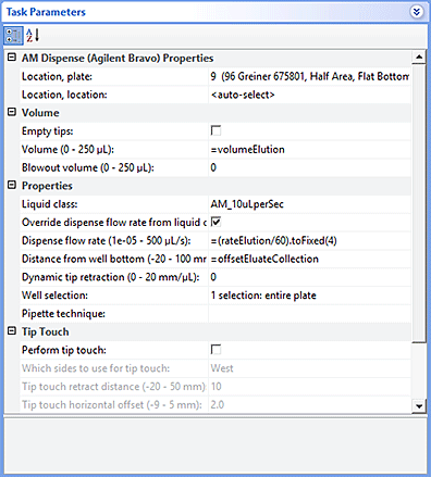
After adding the AM Dispense task at the desired point in the protocol, set the following parameters in the Task Parameters area:
 |
Parameter | Description |
|---|---|
Location, plate | The labware involved in the AM Dispense task. |
Location, location | The location at which the AM Dispense task occurs. <auto-select> automatically places the labware at the first-available or appropriate location for the task. If accessories are installed on the deck, the software uses the accessory configuration information in Bravo Diagnostics to determine the correct location for the task. |
Empty tips | The option to empty all liquid from the probes, cartridges, or tips instead of using the dispense volume specification. |
Volume (0–250 µL) | The volume of liquid to be dispensed from each probe, cartridge, or tip. |
Blowout volume (0–250 µL) | Specifies the volume of air to dispense after the main volume has been dispensed while the probes, cartridges, or tips are still in the wells. Typically, the blowout volume is the same as the pre-aspirate volume. Note: Blowout occurs only in the last quadrant dispensed for a given AM Dispense task. |
Liquid class | The pipetting speed and accuracy. |
Override dispense flow rate from liquid class | The option to override the dispense velocity in the selected liquid class. Selecting this option enables you to specify a value for the dispense flow rate without changing the liquid class. |
Dispense flow rate (1e05–500 µL/s) | The numerical value or the JavaScript variable that will override the dispense velocity setting in the liquid class. A JavaScript variable enables the value to be assigned later. For example, using a VWorks form, an operator could easily change the flow rate for an aspirate step in increments from as low as 1 µL/min up to 2000 µL/min or more using the same liquid class. If the task is included in a VWorks macro, a JavaScript variable enables you to change the value for the task at the macro level. |
Distance from well bottom (-20–100 mm) | The distance between the tips of the probes, cartridges, or disposable tips and the well bottoms during the AM Dispense task. If you specify dynamic tip extension, this is the distance at the end of the AM Dispense task. Use a positive number for tasks that are performed with mounted cartridges, mounted tips, or bare probes at labware other than a cartridge rack. If the task is performed in the upper cup of unmounted cartridges, you can use a negative number for the parameter value. In this case, the well bottom is the top of the cartridge cup, as shown in the following figure. 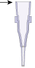 For example, a negative number enables a prewetting step before mounting and priming the cartridges. |
Dynamic tip retraction (0–20 mm/µL) | The rate at which to raise the pipette head during the Dispense task. Use dynamic tip retraction to prevent spills as the pipette tips displace the liquid. To move the tips: • At the same rate as the volume change. Calculate dynamic tip retraction (DTR) as follows: DTR = (well depth)/(well vol) = 1/A, where A is the cross-sectional area of a well with straight walls • Faster than the volume change. DTR > 1/A • Slower than the volume change. DTR < 1/A The starting and ending positions can be calculated as follows: (Vdispensed * DTR) + Distancewell bottom |
Well selection | The wells at which the AM Dispense task occurs. Click in the parameter box, and then click the Browse button to select the wells in the Well Selection dialog box. Use this parameter only if the pipette head has fewer tips than the number of wells in the microplate, or if you are in single-row or single-column mode. |
Pipette technique | The pipette location offset you want to use for the AM Dispense task. The list of pipette techniques are defined in the Pipette Technique Editor. |
Perform tip touch | The option to touch the probes, cartridges, or tips on one or more sides of the well. |
Which sides to use for tip touch | The side or sides of the well to use during tip touch: North, South, East, West, North/South, West/East, West/East/South/North. |
Tip touch retract distance (–20 to 50 mm) | The vertical distance for the probes, cartridges, or tips to rise before touching the sides of the wells. |
Tip touch horizontal offset (–5 to 5 mm) | The horizontal distance the tips move. The value is based on the well diameter specified by the labware definition. For example, if you set a value of: • 0, the tips move a horizontal distance equal to the well radius • > 0, the tips attempt to move past the well radius, which results in a more forceful tip touch • < 0, the tips move a distance less than the radius of the well, resulting in a lighter tip touch |
Quadrant pattern well selection
A quadrant is an evenly spaced array of locations that are accessible by the tips on a pipette head.
Note: For the Bravo 96AM Head, the quadrant pattern option is available only if you are using 384-well microplates.
Instead of a column- or row-wise pattern, you can select a quadrant pattern during well selection.
The quadrant pattern option is available only if:
• The number of channels in the pipette head (or pins in a pin tool) is fewer than the number of wells in the microplate. For example, you can use a 96-channel pipette head to dispense liquid into a 384-well microplate or 1536-well microplate.
• All the channels are selected in the Set Head Mode task when using a pipette head. (The Set Head Mode task is not an option when using a pin tool).
• The liquid-handling task is inside a loop.
To select a quadrant pattern:
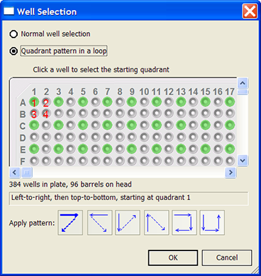
1 In the Task Parameters area, click the Well selection parameter box, and then click the Browse button. The Well Selection dialog box opens. By default, the Normal well selection option is selected. This option is used for column- and row-wise liquid-handling patterns.
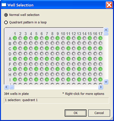 |
2 Select Quadrant pattern in a loop. The contents of the dialog box change. Notice the following:
• Red numbers (1 through 4) appear on wells A1, A2, B1, and B2. The numbers indicate the pipetting sequence: 1 is the starting well, and 4 is the last well. In the following example, the sequence is A1, A2, B1, B2.
• Green wells indicate the starting well in the pipetting sequence.
• Pattern buttons at the bottom of the dialog box indicate the movement of the pipette channels. The movement description is provided in the text box above the buttons.
Note: The last two patterns are unavailable if a group contains 16 wells. For example, the last two patterns are not available if you have a 96-well pipette head and a 1536-well microplate.
 |
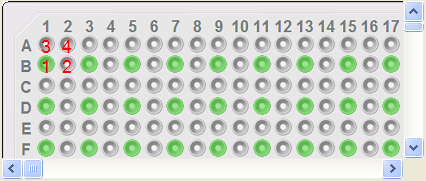
3 Select the starting well. The well becomes green and is labeled 1.
In the following example, the third quadrant (B1 well) is selected.
 |
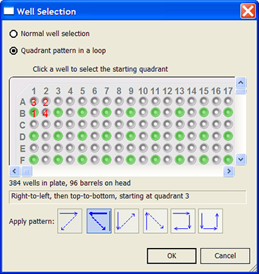
4 Click a pattern button to specify the pipette channel movement. After you click a pattern, the red numbers in the graphic are updated to show the sequence.
In the following example, the second pattern is selected (right-to-left, then top-to-bottom). The third quadrant (B1) is the starting well. The resulting movement is:
Quadrant 3 (B1)
Quadrant 2 (A2)
Quadrant 1 (A1)
Quadrant 4 (B2)
 |
5 When you are finished, click OK to save the changes and return to the VWorks window.
Example: Allowing form’s user to change dispense flow rate using a form edit control
Goal
Allow a form’s user to change the dispense flow rate without modifying the liquid class.
Implementation
In the protocol, the AM Dispense task is added. In the task parameters, the Override dispense flow rate from liquid class check box is selected, and the Dispense flow rate is specified as a variable.
In the VWorks form, an edit control is added for the dispense flow rate using the Dispense flow rate variable. The user can enter values within a specified range in the form and run the protocol using the form. For details on how to design VWorks forms to run protocols, see Creating forms for protocol operators.
Figure Flow rate parameter variable and edit control in a VWorks form
 |
Related information
For information about... | See... |
|---|---|
Using the Bravo 96AM Head | AssayMAP Bravo Platform Getting Started Guide |
AM Aspirate task | |
Aspirate task | |
Dispense task | |
AM Cartridges On | |
AM Cartridges Off | |
Task macros | |
Protocol forms | |
Using JavaScript variables |