Installing and configuring a Magnetic Bead Accessory
About this topic
This topic describes how to set up the Magnetic Bead Accessory on a standard platepad.
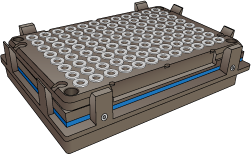
Figure Magnetic Bead Accessory
 |
Before you start
Make sure you have the following:
• Magnetic Bead Accessory
• 1.5 mm hex wrench
• Standard platepad installed at the target deck location
Use the following workflow.
Step | For this task... | See... |
|---|---|---|
1 | Prepare the accessory for installation. | |
2 | Configure the accessory in the profile. | |
3 | Teach the accessory location. |
Preparing the Magnetic Bead Accessory for installation
To prepare the Magnetic Bead Accessory:
1 Place the Magnetic Bead Accessory on a flat surface, and press down on the top of the magnet and then release it to determine if the springs have been removed.
• If the magnet does not spring back up after release, skip to step 3.
• If the magnet springs up again after you release it, proceed to step 2.
2 Perform the following steps to securely mount the magnet to its backing plate without the springs to eliminate any warping:
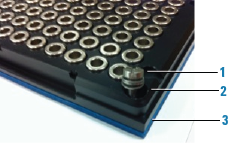
a Remove the four corner screws from the magnet (item 1 in the following figure.
b Remove the springs from between the black plastic magnet mounting (figure, item 2) and metal backing plate (item 3).
 |
c Replace the screws with shorter ones, or use small washers (size M3 works well) to fill the gap and allow the screws to be tightened so that they press the plastic magnet mounting firmly onto backing with the stickerless side facing down.
3 Set the Magnetic Bead Accessory aside temporarily.
In subsequent procedures, you will set the teachpoint at the platepad crosshairs, secure the Magnetic Bead Accessory in place atop the platepad, and then adjust the teachpoint for the accessory.
Configuring the accessory in Bravo Diagnostics
The Magnetic Bead Accessory dimensions are greater than the standard platepad in length (x‑axis) and depth (y‑axis). To ensure that the software takes the dimensions of the accessory into account during automated moves, you should configure the deck location for this accessory in Bravo Diagnostics.
To configure the deck location in the profile:
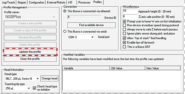
1 In Diagnostics, click the Profiles tab, and verify that the correct profile is open.
2 Click the Configuration tab.
3 In the Locations list, select the deck location of the accessory.
4 Verify that Standard platepad is selected in the Location is configured as list.
5 If you made any changes, click the Profiles tab, and then click Update this profile.
6 VWorks Plus only. If an audit trail is being logged, the Audit Comment dialog box opens. Select or type the audit comment, and then click OK.
Teaching the Magnetic Bead Accessory
To set the deck location teachpoint for the Magnetic Bead Accessory:
1 At the target installation location, make sure that a standard platepad is installed and ensure the Magnetic Bead Accessory is removed from the platepad. Set it aside temporarily.
2 Set the teachpoint to the crosshairs of the platepad. For instructions, see Setting the first teachpoint.
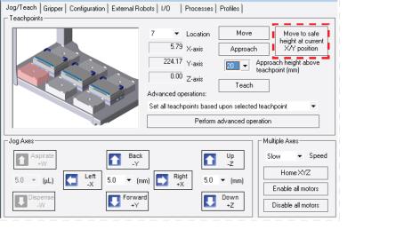
3 Raise the head up in the z-axis by 29.6 mm using the Jog Axes controls in the Jog/Teach tab.
Click Teach.
4 Click Move to safe height at current X/Y position.
 |
5 Reposition the Magnetic Bead Accessory on the platepad, as shown in the following figure (1). Ensure that the accessory is fully seated on the platepad.
Figure Magnetic Bead accessory on top of a standard platepad
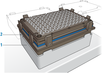 |
6 Using the 1.5 mm wrench, tighten the set screw in the tab, as shown in preceding figure (2), to secure the base to the platepad.
7 In the Jog/Teach tab image of the Bravo deck, click the accessory Location.
8 In the Approach height above teachpoint list, select 2 mm, and then click Approach.
The Bravo head moves to the deck location and moves down so that the pipette tip is approximately 2 mm above the Magnetic Bead Accessory.
9 Verify that the pipette tips are centered above the magnet rings in the x‑ and y‑axes.
If necessary, adjust the x- and y-axes at this point, and then jog the head down by 2 mm to the teachpoint z‑axis and click Teach.
10 In the Profiles tab, click Update this profile to save the changes.
 |
11 VWorks Plus only. If an audit trail is being logged, the Audit Comment dialog box opens. Select or type the audit comment, and then click OK.
Related information
For information about... | See... |
|---|---|
Bravo Platform hardware components | |
Editing teachpoints |