Setting up the Thermal Station (cooling pad)
About this topic
This topic describes how to install the Thermal Station (cooling pad) on a Bravo deck location.
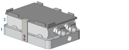
The Thermal Station uses a fluid-filled thermal block to provide temperature control of ±0.1°C uniformly across a microplate. The Thermal Station consists of the following:
• A deck positioner (figure, 1) that attaches to the deck
• A cold plate (figure, 2) that installs on the deck positioner
• A liquid chilling unit and tubing (not shown) that supplies the chilled fluid to the Thermal Station.
 |
The Thermal Station is available with the drain ports on the short end or long side of the accessory. Typically, the drain ports are on the short end and the tubing is routed off the side of the Bravo deck. A Thermal Station that has the drain ports on the long end may be installed in the back row of the Bravo deck with the tubing routed out the rear. Use the following procedure to install either option.
Setup workflow
Step | Procedure | See… |
|---|---|---|
1 | Install the Thermal Station at the Bravo deck location. | |
2 | Configure the deck location for this accessory in the Bravo profile. | |
3 | Edit the teachpoint. Note: Earlier model cold plates may not have a crosshairs. In this case, use the teach plate. Be sure to consider the 10‑mm thickness of the teach plate when you edit the teachpoint. | |
4 | Complete the hardware setup. |
Installing the Thermal Station
Before you start
Make sure you have the following:
• Thermal Station, including the deck positioner and socket-head screw that fastens the deck positioner to the deck
• Hex wrenches: M1.5, M2, and M5
• Plumber’s tape
• Liquid chilling unit, tubing, and manufacturer user documentation
Procedure
To install the Thermal Station:
1 If a platepad is installed at the target location, uninstall the platepad as follows:
Uninstall the M6 screw in the center of the platepad and then lift the platepad off of the deck.
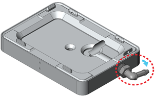
2 Prepare the aluminum deck positioner, as follows:
a Using plumber’s tape, install the appropriate plug in the corresponding drain hole on the deck positioner:
• Elbow plug (part G5550‑24200) on short side
• Straight plug (part G5550-16025) on long side
b Set the plug angle slightly lower than parallel to the deck positioner to allow draining.
c Ensure that a plug is installed in the unused drain hole using plumber’s tape. For example, if you installed the elbow plug on the short side, ensure that the drain on the long side is plugged.
Note: For easier access to the bracket screws, you may prefer to temporarily install the side brackets on deck positioner before performing the next step.
Figure Deck positioner with elbow plug installed on the short end
 |
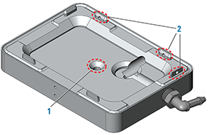
3 Install the deck positioner at the target deck location:
a Orient the deck positioner so that the elbow plug is on an outside edge of the deck and facing the direction of the tubing path.
b Align the deck positioner dowel pins with the holes on the deck, and make sure the deck positioner sits level on the deck.
Note: If necessary, use a rubber mallet to tap the deck positioner until it sits level on the deck.
c Insert the screw into the center of the deck positioner and tighten. See the following figure, item 1.
d Ensure that the setscrews in the deck positioner tabs (figure, 2) are recessed. Use a M1.5 hex wrench to back out any protruding setscrews.
 |
4 Inspect the cold plate to ensure no bowing is visible along its length at the top and bottom.
 |
5 Place the cold plate on top of the deck positioner. Make sure the cold plate is level and fully seated on the deck positioner.
6 Using an M1.5 hex wrench, tighten the setscrews on the deck positioner tabs as follows:
a Tighten the setscrew on the end tab.
b Tighten the setscrews in the two side tabs.
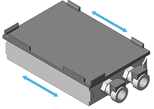
7 Install the side brackets as follows:
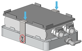 |
a Position the brackets, aligning the slots in the brackets with the screw holes in the deck positioner.
b Install the two hex screws in each bracket, and then apply downward pressure on the bracket tops while tightening the hex screws.
Ensure that both brackets are holding the cold plate securely in place.
Configuring the deck location in the profile
Configuring this deck location as a Thermal Station enables the Bravo gripper to safely transfer labware to and from that location even if a thermal plate insert is seated on the Thermal Station. During a transfer, the Bravo gripper raises the labware 30 mm (z‑axis) before moving it from the Thermal Station.
To configure the deck location:
1 In Bravo Diagnostics, click the Profiles tab, and verify that the correct profile is selected.
2 In the Configuration tab. Location is configured as list, select Accessory.
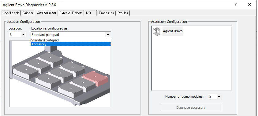 |
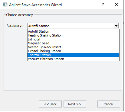
3 Follow the instructions in the Accessories Wizard to:
a Specify the Location of the installed accessory.
Note: Your selection in the Accessories Wizard overrides the default selection in the Configuration tab.
b Select Thermal Station in the Accessory list.
 |
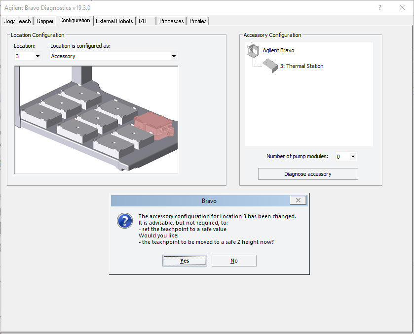 |
4 In the configuration message, click Yes to move the teachpoint to a safe height.
5 Set the teachpoint for the Thermal Station using the same procedure that you would for a platepad.
Note: This accessory configuration accounts for the extra height of the Thermal Station, which is approximately 20 mm taller than a standard platepad
6 In the Profiles tab, click Update this profile.
7 VWorks Plus only. If an audit trail is being logged, the Audit Comment dialog box opens. Select or type the audit comment, and then click OK.
Completing the hardware setup
After installing the Thermal Station and adjusting the teachpoint, the following setup tasks must be completed before the accessory is ready for use.
Step | Procedure | See… |
|---|---|---|
1 | Connect one end of the marprene tubing to the cooling unit drain and place the other end in a waste container. | Liquid chilling unit manufacturer’s user documentation |
2 | Install the straight ends of the thermal tubing into the Thermal Station, and connect the other ends into the cooling unit. | Liquid chilling unit manufacturer’s user documentation |
3 | Connect the power cord from cooling cube to an AC outlet. | Liquid chilling unit manufacturer’s user documentation |
4 | Fill the liquid chilling unit as follows: a Turn on the unit. b Watch for the Liquid Level Low message to display on the front panel. c Turn off the unit and fill it with 25% EtOH or cooling fluid recommended by manufacturer. d Repeat steps a to c. The unit should hold 600 to 700 mL. | Liquid chilling unit manufacturer’s user documentation |
5 | Make sure the unit is on, and set the temperature on the front display. Press ENTER and then press START/STOP to start the cooling. Verify that the Thermal Station gets cold. | Liquid chilling unit manufacturer’s user documentation |
Related information
For information about… | See… |
|---|---|
Verifying and setting the teachpoint for the accessory | |
Using the accessory in a protocol | VWorks Automation Control User Guide |