Hardware overview
About this topic
This topic describes the Microplate Labeler hardware features, including the optional barcode reader.
Front view
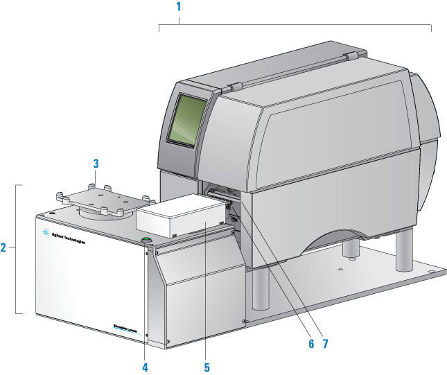
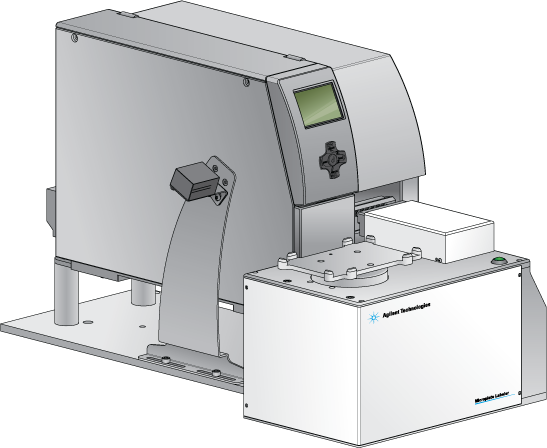
The Microplate Labeler is comprised of a barcode applicator and label printer assembled on a baseplate.
Figure Microplate Labeler components (front view)
 |
Item | Feature | Description |
|---|---|---|
1 | Printer | Prints a label (600 dpi) and pauses when the label reaches the peelbar to allow the applicator head to retrieve the printed label. The printer supports the printing of linear or two-dimensional (2D) barcodes. A Microplate Labeler that is fitted with the cab SQUIX model printer has a touchscreen. For details, see Using the cab SQUIX printer touchscreen. The cab A2+ model printer has a display and navigation pad. For details, see Using the cab A2+ printer display and navigator pad. |
2 | Applicator | Contains the plate stage, applicator head, green button, electronics, and the connection panel (back side) for the device. |
3 | Plate stage | Provides a platform to support a plate delivered by a robot or a person. The plate stage rotates side to side to enable labeling on all four sides of a microplate. The plate stage rotation also allows the optional barcode reader to read any side of a microplate. The plate stage can move up and down to provide a choice of two vertical labeling positions to accommodate labware of varying heights. |
4 | Green button | Starts a print-and-apply operation for printing test labels. |
5 | Applicator head | Rotates between the printer and the plate stage. Uses vacuum pads (suction cups) to pick up a printed label from the printer and apply the label to a microplate on the plate stage. |
6 | Vacuum pads | Uses vacuum to pick up a label from the printer and uses compressed air to apply the label to a microplate on the plate stage. |
7 | Printer peelbar | Provides a platform for presenting each label to the applicator head vacuum pads. As the label strip travels over the peelbar, each label lifts off the label backing slightly to allow the applicator head to pick up the label. |
Connection panel (back view)
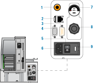
The Microplate Labeler connection panel is on the back of the applicator, next to the printer.
Figure Microplate Labeler connection panel (back view)
 |
Item | Feature | Description |
|---|---|---|
1 | Air supply port | Connects to a compressed-air source. The device uses compressed air to: • Move the plate stage up and down • Rotate the applicator head side to side • Extend and retract the applicator head • Create a vacuum that the applicator head uses to pick up labels from the printer • Apply labels to a microplate |
2 | Ethernet port | Connects an Ethernet cable from the controlling computer to the Microplate Labeler for communication. |
3 | Barcode reader port | Connects the cable from the optional barcode reader to the Microplate Labeler for communication. |
4 | Serial port | Connects a serial cable from the controlling computer to the Microplate Labeler to provide serial communication. You can use the 1.8‑m (6-ft) serial-communications cable (beige) provided in the Microplate Labeler utility kit. Note: If you connect to the Microplate Labeler using the serial port, you do not use the Ethernet port. |
5 | Power switch | Turns on (|) or off (o) the power. |
6 | AC power port | Connects the power cable. |
7 | Pressure gauge | Indicates the regulated air pressure. |
8 | Air pressure regulator | Regulates the incoming air pressure to ensure that the device’s internal components are not exposed to air pressure that is too high. |
9 | Fuse holder | Houses the electrical fuse. |
Printer overview
Printer front view
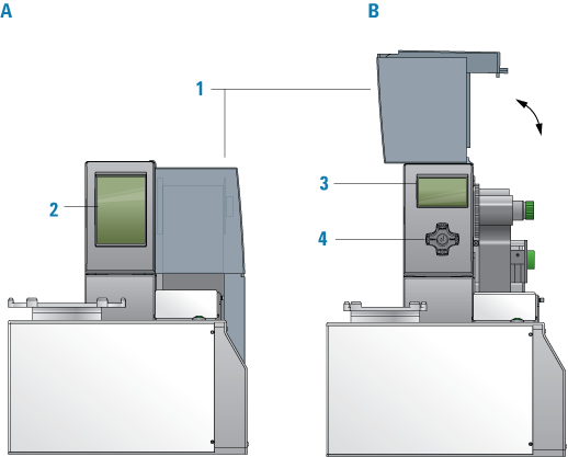
Figure Printer front view (A) cab SQUIX printer, (B) cab A2+ printer
 |
Item | Feature | Description |
|---|---|---|
1 | Cover | Removable transparent plastic cover that opens to provide access for cleaning the printer components and changing the media. |
2 | cab SQUIX printer touchscreen | Displays the Ready message and various messages for service, and provides access to the Help menu that contains how-to videos for maintaining the printer. For details, see Using the cab SQUIX printer touchscreen. |
3 | cab A2+ printer service display | Displays the Ready message and various messages for service. For details, see Using the cab A2+ printer display and navigator pad. |
4 | cab A2+ service navigator pad | Used by the factory and field service personnel to set up the printer or change settings on the printer. |
Printer side view
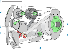
Figure Printer side view with cover removed
 |
Item | Feature | Description |
|---|---|---|
1 | Ribbon supply hub | Holds the unused printer ribbon roll. The printer requires the Microplate Labeler Media Kit (not shown), which contains the thermal transfer ribbon and labels for the printer. |
2 | Ribbon take-up hub | Rewinds the used ribbon. |
3 | Printhead (hidden under the ribbon) | The narrow bar that presses the image through the ribbon and onto the label as the media move into position on to the print roller. |
4 | Print roller and rewind assist roller | The rollers that assist in moving the label strip under the printhead (print roller) and to the internal rewinder. |
5 | Internal rewinder | Rewinds and holds the used label strip. |
6 | Roll retainer | Holds the unused label roll. |
7 | Margin stop | Locks the roll retainer and holds the ribbon roll securely in place. |
Barcode reader
The optional barcode reader is connected to the Microplate Labeler so that it can be used with the software to verify or clone barcodes.
Figure Microplate Labeler with barcode reader installed
 |
Related information
For information about... | See... |
|---|---|
Barcodes | |
The labeling process | |
How to install and use the barcode reader | Agilent Technical Support |