Setting and managing teachpoints
About this topic
This topic describes teachpoints and how to set them.
Teachpoints defined
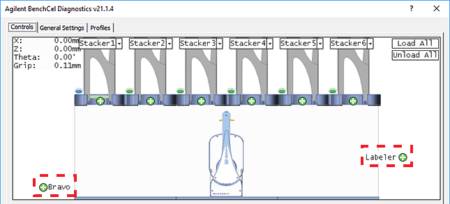
A teachpoint is a set of coordinates that define where the robot can pick up or place labware. The location can be on an external device or a platepad. You set, edit, and save teachpoints in BenchCel Diagnostics. The teachpoints are displayed as plus signs ( ) in the graphical display area in the BenchCel Diagnostics dialog box.
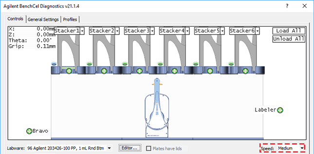
) in the graphical display area in the BenchCel Diagnostics dialog box.Note: The graphical display area also shows teachpoints () at the stacks. These teachpoints are preset at the factory and should not be changed.
) at the stacks. These teachpoints are preset at the factory and should not be changed.Figure Example teachpoints for labware pickup and placement location at integrated devices
 |
Teachpoint files
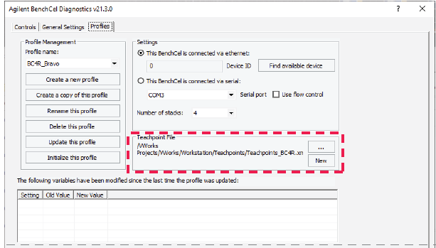
The teachpoints you set are saved in the XML format in a teachpoint file. The default teachpoint file name is Teachpoints_<profilename>.xml, where <profilename> is the name of the profile. The Teachpoint File area in the Profiles page displays the file path.
You must use one teachpoint file for each BenchCel device. If you integrate a new device with the BenchCel Microplate Handler, you can add the new teachpoints to the existing file. If you have multiple BenchCel devices in a workstation, you must create a teachpoint file for each BenchCel device in the workstation.
The teachpoint file is referenced by a profile. For information about profiles, see Creating profiles.
Workflow for setting teachpoints
Step | For this step… | See… |
|---|---|---|
1 | Determine the teachpoint coordinates. | |
2 | Lock the position of the integrated device. | |
3 | Record the teachpoint. | |
4 | Verify the teachpoint. | |
5 | Edit the teachpoint, if required. |
Before you start
• Verify that the labware you want to use has a corresponding labware entry in the software. To view the labware entries, click Tools > Labware Editor in the VWorks window.
Determining the teachpoint coordinates
To determine the coordinates of the pickup and placement location:
1 Place two or three spare microplates in a labware rack, and then install the rack on the BenchCel Microplate Handler. For instructions, see Filling and emptying the labware racks and Installing and uninstalling the labware racks.
2 Open BenchCel Diagnostics for the BenchCel device that you are setting up.
3 On the Profiles page, look in the Teachpoint File area to make sure the correct teachpoint file is loaded. You will be adding new teachpoints to this file.
 |
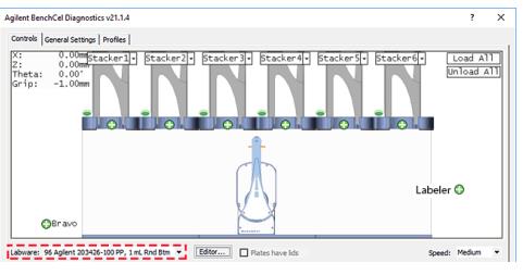
4 In the Controls tab, select the labware definition from the Labware list.
 |
5 In the graphical display area, click Stacker at the top of the rack that contains the spare microplates. In the menu that appears, click Load plates.
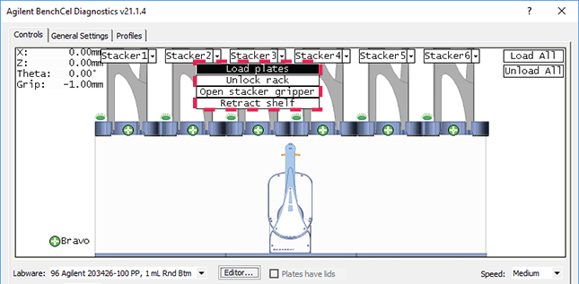 |
The BenchCel device moves the stack down and holds the stack in the stacker grippers, or supports the stack on the stacker shelf, as specified in the labware definition.
6 In the graphical display area, click the plus sign () at the stacker head that contains the spare microplates. In the menu that appears, click Downstack from Stacker.
) at the stacker head that contains the spare microplates. In the menu that appears, click Downstack from Stacker. 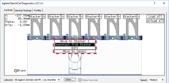 |
The robot head moves under the stacker and holds the first spare microplate in its grippers.
7 On the Controls page, click the Jog/Teach tab.
8 Click Go Home. The robot head moves to its home position at the center of the BenchCel Microplate Handler.
Note: The microplate is still in the robot grippers from step 6.
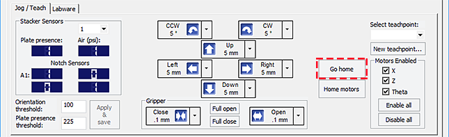 |
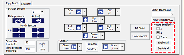
9 In the Motors Enabled area, clear the check boxes for X and Theta to disable the x‑axis and theta‑axis motors. The z‑axis motor is still enabled (the Z box is selected).
 |
10 With the robot grippers holding the spare microplate, gently push or pull the robot head and arms close to the teachpoint location. Position the robot head and arms so that the microplate rests in the target microplate location.
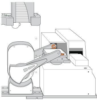 |
11 To fine-tune the teachpoint until you are able to place the microplate in the target location, use the following methods:
• Visually inspect the position of the microplate relative to the plate stage. If the robot is not aligned with the plate stage along the y-axis (front-to-back direction), move the robot into the safe zone, physically slide the external device and its integration plate along the y-axis, move the robot back and see if the robot arms are aligned with the plate stage. You might have to loosen the clamp screw to slide the device (see About integrating devices in a BenchCel Workstation).
• To move the robot head up or down in small, precise increments, open BenchCel Diagnostics. On the Controls page Jog/Teach tab, select the jog increment from the corresponding list, and then click Up ( ) or Down (
 ).
).
) or Down (). |
• With the x-axis and theta-axis motors disabled, gently push or pull the robot side to side so that the robot arms are able to place the microplate on the plate stage.
The microplate should sit level on the target location. In addition, the robot arms should not come in contact with any part of the target platepad, plate stage, or other surfaces.
12 Visually inspect the position of the microplate on the target location. It should be centered on the location. If it is not, ensure that the x-axis and theta-axis motors are disabled on the Jog/Teach tab, and then manually move the robot head to the microplate at the location.
Locking the device positions
Before you record the teachpoint, lock the devices in their positions.
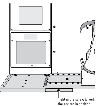
To lock the devices in their positions:
1 Tighten the BenchCel integration plate clamp screw using the 3-mm hex wrench.
2 Check the teachpoint coordinates again. See Determining the teachpoint coordinates.
 |
Recording the teachpoint coordinates
To record the teachpoint coordinates in BenchCel Diagnostics:
1 Ensure the robot is holding the microplate at the teachpoint location.
2 On the Controls page Jog/Teach tab, click New teachpoint.
3 In the Teachpoint Details dialog box, click Use current positions. The robot’s current coordinates fill the Theta, X, and Z boxes.
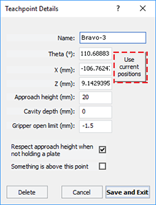 |
Setting | Comment |
|---|---|
Theta | The angle that the robot arms are from their home position, in degrees. A positive value moves the arms counterclockwise from the home position. A negative value moves the arms are clockwise from the home position. The range of movement is from ‑115° to 115°. |
X | The horizontal distance (mm) from the home position. A positive value moves the robot head to the right of the home position. A negative value moves the robot head to the left of the home position. The range of movement depends on the number of stacker heads. For two stacker heads, the range is from –145 mm to 145 mm. |
Z | The vertical distance (mm) from the home or lowest z‑axis position. A positive value moves the robot head up from the home position. A negative value moves the head down from the home position. The range of movement is from ‑1.5 mm to 104 mm. |
4 Set the remaining teachpoint parameters and options in the Teachpoint Details dialog box:
Setting | Comment |
|---|---|
Name | Type a one-word name for the teachpoint. For example, if the teachpoint is on an integrated Microplate Labeler, you might want to name the teachpoint Labeler. This name appears in the graphical display area in the BenchCel Diagnostics dialog box. |
Approach height | Type the height clearance (mm) the robot must maintain above the teachpoint as it moves towards or away from the teachpoint location. The valid range is from 0 mm to 40 mm. 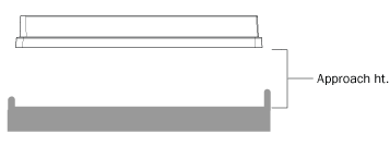 Use this setting to prevent the robot from colliding with raised tabs or walls at the teachpoint location. You can start with an approach height of 20 mm (default). However, if there is an obstruction above the teachpoint, a smaller approach height might be required to prevent a collision. Note: This value applies when the robot is holding a microplate. When it is not holding a microplate, the robot will approach the teachpoint at the height of the teachpoint, unless you select the Respect approach height when not holding a plate option. |
Cavity depth | This setting is not commonly used and should be set at 0 mm for most applications. You can use this setting to account for teachpoints that have a depth (or negative height). To do this, type the depth (mm) as an offset to the Robot gripper offset. A positive value causes the grippers to grab higher on the plate by the specified amount. A negative values causes the grippers to grab lower on the plate. For example, suppose the Robot gripper offset is 5 mm and the platepad you want to use has depth of 9 mm. When the microplate sits in the platepad, the robot grippers cannot reach the offset height, as the following diagram shows. To account for this depth, you can set the Cavity depth at –9 mm. The robot grippers will grip the microplate 9 mm above the 5 mm offset (at 14 mm). 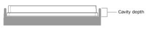 |
Gripper open limit | Type the maximum distance (mm) the robot grippers are allowed to open as they prepare to grip the microplate at the teachpoint. The maximum value you set is less than or equal to the Robot Gripper Open Position value set in the BenchCel Diagnostics Controls Labware tab. Use this setting if the teachpoint area is narrower than the robot grippers open position. (To see this value, click Save and exit, and then click the Labware tab in the BenchCel Diagnostics Control tab.) Note: This value is used only at the teachpoint and not during other operations. |
Respect approach height when not holding a plate | Select the check box to use the approach height even when the robot is not holding labware. |
Something is above this point | Select the option to limit the robot’s movements within the robot safe zone. With this selection, the robot will move only along the theta-axis as long as all of its parts (head, arms, grippers, and labware) are within the safe zone when approaching or moving away from the teachpoint. 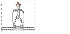 Clear the check box to allow the robot to use the full workspace. The robot’s theta-axis movements are not limited when approaching and moving away from the teachpoint. 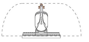 Use this option to limit the robot’s movements to prevent collision when approaching a teachpoint. For example, when moving labware to and from a multi-shelf device such as the Vertical Pipetting Station, this option prevents the robot from colliding with the shelf above the target teachpoint. |
5 Click Save and Exit to save the teachpoint in the teachpoint file and close the Teachpoint Details dialog box.
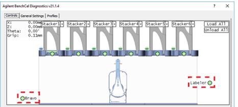
On the Controls page in BenchCel Diagnostics, the new teachpoint appears in the graphical display area as a plus sign ().
).Figure Example of teachpoints for labware pickup and placement locations on external devices
 |
6 Gently push or pull the robot into the safe zone.
7 On the Jog/Teach tab, click Go Home. The software prompts you to enable all the motors. After the motors are enabled, the robot head moves to the center of the BenchCel device, and the robot arms are perpendicular to the x-axis. The robot grippers are still holding the spare microplate you used to set the teachpoint.
8 On the Controls page, click the plus sign () of the stacker that is holding the spare microplates, and then choose Upstack to Stacker. The robot moves the microplate back into the stack.
) of the stacker that is holding the spare microplates, and then choose Upstack to Stacker. The robot moves the microplate back into the stack.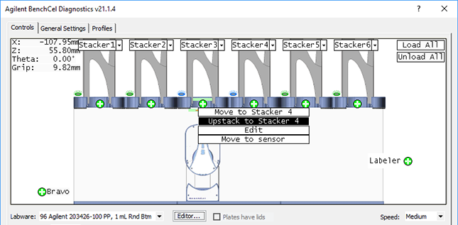 |
9 Save the device file.
10 VWorks Plus only. If an audit trail is being logged, the Audit Comment dialog box opens. Select or type the audit comment, and then click OK.
Verifying the teachpoints
To verify a teachpoint:
1 Load two to three spare microplates in the labware rack and load the rack on the BenchCel device. For instructions, see Filling and emptying the labware racks and Installing and uninstalling the labware racks.
2 In BenchCel Diagnostics, click the Controls tab, and select the desired labware definition from the Labware list.
3 In the graphical display area, click the plus sign () at both of the following locations:
) at both of the following locations:• The stack that contains the spare microplates
• The teachpoint you want to verify
The selected teachpoints should be highlighted in red circles ( ).
).
).4 In the Speed list, select Slow.
Note: You can set the Slow speed as a percentage of the factory-set maximum speed. To do this, see Changing the robot speed.
 |
5 In the graphical display area, click the stacker that contains the spare microplates. In the command menu that appears, click Transfer to <teachpoint name>, where <teachpoint name> is the name of the teachpoint you are verifying. The robot picks up the first microplate in the stack and moves it to the selected teachpoint.
• If the robot did not move the microplate to the correct location, proceed to Editing existing teachpoints to refine the teachpoint.
• If the robot correctly placed the microplate at the new teachpoint, move the microplate back to the stack as follows:
In the graphical display area, click the plus sign () at the new teachpoint, and then choose Transfer to Stack. The robot moves the microplate from the teachpoint back to the stack.
) at the new teachpoint, and then choose Transfer to Stack. The robot moves the microplate from the teachpoint back to the stack.Editing existing teachpoints
When you set a teachpoint for the first time, you will likely set, verify, and edit the teachpoint a number of times to ensure that the teachpoint is correct. After the teachpoint is correct, no further teachpoint adjustment is required unless you do the following:
• Move the BenchCel Microplate Handler
• Move or replace one of the devices in the workstation
• Adjust settings on the devices
To edit an existing teachpoint:
1 In BenchCel Diagnostics, click the Profiles tab, and verify that the correct teachpoint file is loaded.
2 Click the Controls tab. In the graphical display area, double-click the plus sign () of the teachpoint you want to edit.
) of the teachpoint you want to edit.Figure Example of teachpoints for external devices
|
The Teachpoint Details dialog box opens and displays the current coordinates and settings for the selected teachpoint.
3 Do one of the following:
• Follow the instructions in Determining the teachpoint coordinates to manually move the robot head to a new teachpoint position and set the teachpoint.
• Type new coordinate values or change any of the existing settings.
4 Click Save and Exit to save the revised teachpoint in the teachpoint file.
5 VWorks Plus only. If an audit trail is being logged, the Audit Comment dialog box opens. Select or type the audit comment, and then click OK.
Deleting teachpoints
To delete a teachpoint:
1 In BenchCel Diagnostics, click the Profiles tab, and verify that the correct teachpoint file is loaded.
2 In the graphical display area, double-click the plus sign () of the teachpoint you want to delete.
) of the teachpoint you want to delete.3 In the Teachpoint Details dialog box, click Delete. The current teachpoint file will automatically be updated when you delete a teachpoint.
4 Save the device file.
5 VWorks Plus only. If an audit trail is being logged, the Audit Comment dialog box opens. Select or type the audit comment, and then click OK.
Related information
For information about | See... |
|---|---|
Setup procedure | |
Integrating external devices | |
Moving between teachpoints |